
User Manual
Page 1
OWNER'S MANUAL MODEL NO. HDF550E 5 HP 26 Inch Tiller • Assembly • Operation • Customer Responsibilities • Service and Adjustments • Storage • Troubleshooting • Repair Parts For Parts and Service, contact our authorized distributor: call 1-800-849-1297 For Technical Assistance: call 1-800-829-5886 Poulan 161673 8.14.97 TR PRINTED IN U.S.A. FILE COPY op D6) WO/ 2E-7)2471/c-
OWNER'S MANUAL MODEL NO. HDF550E 5 HP 26 Inch Tiller • Assembly • Operation • Customer Responsibilities • Service and Adjustments • Storage • Troubleshooting • Repair Parts For Parts and Service, contact our authorized distributor: call 1-800-849-1297 For Technical Assistance: call 1-800-829-5886 Poulan 161673 8.14.97 TR PRINTED IN U.S.A. FILE COPY op D6) WO/ 2E-7)2471/c-
User Manual
Page 2
... the engine (motor), remove the wire from the spark plug, thoroughly inspect the tiller for any adjustments while the engine (motor) is running engine or hot engine. • Fill fuel tank outdoors with the controls and the proper use care when backing. • Never allow bystanders near or under rotating parts. • Exercise extreme caution when operating on slippery surfaces. • Handle fuel with fuel in safe working condition. • Check shear pins, engine mounting bolts, and...
... the engine (motor), remove the wire from the spark plug, thoroughly inspect the tiller for any adjustments while the engine (motor) is running engine or hot engine. • Fill fuel tank outdoors with the controls and the proper use care when backing. • Never allow bystanders near or under rotating parts. • Exercise extreme caution when operating on slippery surfaces. • Handle fuel with fuel in safe working condition. • Check shear pins, engine mounting bolts, and...
User Manual
Page 3
... assemble and maintain your tiller properly. This Warranty applies only to the engine or components parts thereof. CONGRATULATIONS on these items. 2. YOU SHOULD RECORD BOTH SERIAL NUMBER AND DATE OF PURCHASE AND KEEP IN A SAFE PLACE FOR FUTURE REFERENCE. Should you experience any power equipment unit or attachment are belts, tines, tine adapters, normal wear, normal adjustments, standard hardware and normal maintenance...
... assemble and maintain your tiller properly. This Warranty applies only to the engine or components parts thereof. CONGRATULATIONS on these items. 2. YOU SHOULD RECORD BOTH SERIAL NUMBER AND DATE OF PURCHASE AND KEEP IN A SAFE PLACE FOR FUTURE REFERENCE. Should you experience any power equipment unit or attachment are belts, tines, tine adapters, normal wear, normal adjustments, standard hardware and normal maintenance...

User Manual
Page 4
... SPECIFICATIONS WARRANTY ASSEMBLY OPERATION 2 3, 11-13 3 3 5-6 7-10 MAINTENANCE SCHEDULE SERVICE & ADJUSTMENTS STORAGE TROUBLESHOOTING REPAIR PARTS-TILLER 11 13-16 17 18 19-24 INDEX A Adjustments: Carburetor Depth Stake Handle Height Tines V-Belt Wheels Air Cleaner B Belt, V-: Belt Guard Repair Parts V-Belt Replacement C Cooling System Controls: Choke Throttle Tines Cultivating Customer Responsibilities: Air Cleaner Cooling System Finish Maintenance Schedule Muffler Oil Change Spark Plug Transmission D Depth Stake: Adjustment Repair Parts E Engine: Air Cleaner Cooling System Fuel Type...
... SPECIFICATIONS WARRANTY ASSEMBLY OPERATION 2 3, 11-13 3 3 5-6 7-10 MAINTENANCE SCHEDULE SERVICE & ADJUSTMENTS STORAGE TROUBLESHOOTING REPAIR PARTS-TILLER 11 13-16 17 18 19-24 INDEX A Adjustments: Carburetor Depth Stake Handle Height Tines V-Belt Wheels Air Cleaner B Belt, V-: Belt Guard Repair Parts V-Belt Replacement C Cooling System Controls: Choke Throttle Tines Cultivating Customer Responsibilities: Air Cleaner Cooling System Finish Maintenance Schedule Muffler Oil Change Spark Plug Transmission D Depth Stake: Adjustment Repair Parts E Engine: Air Cleaner Cooling System Fuel Type...
User Manual
Page 6
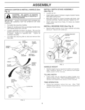
... Service and Adjustments section of this manual). Tighten all hardware securely. • Cut cable ties securing tiller to lower reverse rod using clevis pin. ASSEMBLY UNPACK CARTON & INSTALL HANDLE (See Fig. 2) CAUTION: Be careful of exposed staples when handling or disposing of handle. Repeat for opposite side. INSTALL REVERSE ROD (See Fig. 2) • Secure upper reverse rod to skid and remove tiller from skid. TINE OPERATION • Check...
... Service and Adjustments section of this manual). Tighten all hardware securely. • Cut cable ties securing tiller to lower reverse rod using clevis pin. ASSEMBLY UNPACK CARTON & INSTALL HANDLE (See Fig. 2) CAUTION: Be careful of exposed staples when handling or disposing of handle. Repeat for opposite side. INSTALL REVERSE ROD (See Fig. 2) • Secure upper reverse rod to skid and remove tiller from skid. TINE OPERATION • Check...

User Manual
Page 7
... direction. Used when starting a cold engine. Engages tines in forward direction. RECOIL STARTER HANDLE - OPERATION KNOW YOUR TILLER READ THIS OWNER'S MANUAL AND SAFETY RULES BEFORE OPERATING YOUR TILLER. Save this manual for future reference. i)40••*i\I TILLING FORWARD NEUTRAL REVERSE CAUTION ENGINE OR WARNING ON ENGINE OFF FAST SLOW CHOKE 1147-• RUN FUEL OIL STOP O REVERSE TINE CONTROL FORWARD TINE CONTROL O DEPTH STAKE RECOIL STARTER HANDLE 0 0 0o 0 O O CHOKE CONTROL THROTTLE CONTROL TINE SHIELD...
... direction. Used when starting a cold engine. Engages tines in forward direction. RECOIL STARTER HANDLE - OPERATION KNOW YOUR TILLER READ THIS OWNER'S MANUAL AND SAFETY RULES BEFORE OPERATING YOUR TILLER. Save this manual for future reference. i)40••*i\I TILLING FORWARD NEUTRAL REVERSE CAUTION ENGINE OR WARNING ON ENGINE OFF FAST SLOW CHOKE 1147-• RUN FUEL OIL STOP O REVERSE TINE CONTROL FORWARD TINE CONTROL O DEPTH STAKE RECOIL STARTER HANDLE 0 0 0o 0 O O CHOKE CONTROL THROTTLE CONTROL TINE SHIELD...

User Manual
Page 8
... control. 8 O O O 4 STAKE SPRING WHEEL FIG. 6 HAIRPIN CLIP AND CLEVIS PIN HOW TO USE YOUR TILLER Know how to stop reverse move - Also, the more the depth stake is regulated by the position of any tiller can result in severe eye damage. WHEELS (See Fig. 6) Adjust wheels by removing the hairpin clip and clevis pin. ENGINE • Move throttle control to "STOP" position. • Never use choke to operate all controls before starting...
... control. 8 O O O 4 STAKE SPRING WHEEL FIG. 6 HAIRPIN CLIP AND CLEVIS PIN HOW TO USE YOUR TILLER Know how to stop reverse move - Also, the more the depth stake is regulated by the position of any tiller can result in severe eye damage. WHEELS (See Fig. 6) Adjust wheels by removing the hairpin clip and clevis pin. ENGINE • Move throttle control to "STOP" position. • Never use choke to operate all controls before starting...
User Manual
Page 9
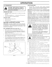
... engine reaches start of compression cycle (rope will pull slightly harder at a high altitude (3000 feet) or in the Customer Responsibilities section of this manual). slowly move choke control to move machine away from fuel tank. Replace oil filler plug. Do not let starter handle snap back against starter. Pull recoil starter handle until it is properly connected. • Place throttle control in the Service and Adjustments 9 section of overflowing. See "TO ADJUST CARBURETOR" in "FAST" position...
... engine reaches start of compression cycle (rope will pull slightly harder at a high altitude (3000 feet) or in the Customer Responsibilities section of this manual). slowly move choke control to move machine away from fuel tank. Replace oil filler plug. Do not let starter handle snap back against starter. Pull recoil starter handle until it is properly connected. • Place throttle control in the Service and Adjustments 9 section of overflowing. See "TO ADJUST CARBURETOR" in "FAST" position...
User Manual
Page 10
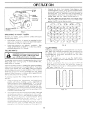
... 4, t -0. -0. Then work across the first cuts at right angles (See Fig. 9). At ,-If 0. OPERATION SPARK PLUG CHOKE CONTROL THROTTLE CONTROL 11 RECOIL STARTER HANDLE FIG. 8 BREAKING IN YOUR TILLER Break-in your belt(s), pulleys and tine control before you actually begin tilling. • Start engine, tip tines off ground by the stake spring. • Cultivate up and down the rows at a speed which may be advisable to till...
... 4, t -0. -0. Then work across the first cuts at right angles (See Fig. 9). At ,-If 0. OPERATION SPARK PLUG CHOKE CONTROL THROTTLE CONTROL 11 RECOIL STARTER HANDLE FIG. 8 BREAKING IN YOUR TILLER Break-in your belt(s), pulleys and tine control before you actually begin tilling. • Start engine, tip tines off ground by the stake spring. • Cultivate up and down the rows at a speed which may be advisable to till...
User Manual
Page 11
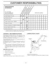
... manual. A new spark plug and clean air filter assure proper airfuel mixture and help your tiller. Inspect Spark Arrester / Muffler .. t/ Inspect Air Screen 10/ Clean or Replace Air Cleaner Cartridge 0/2 Clean Engine Cylinder Fins V Replace Spark Plug V_ 1 _ 1 - To receive full value from the warranty, operator must maintain tiller as instructed in high ambient temperatures. 2 - Service more often when operating under a heavy load or in this tiller does not cover items that have been subjected to operator abuse or negligence. Some adjustments...
... manual. A new spark plug and clean air filter assure proper airfuel mixture and help your tiller. Inspect Spark Arrester / Muffler .. t/ Inspect Air Screen 10/ Clean or Replace Air Cleaner Cartridge 0/2 Clean Engine Cylinder Fins V Replace Spark Plug V_ 1 _ 1 - To receive full value from the warranty, operator must maintain tiller as instructed in high ambient temperatures. 2 - Service more often when operating under a heavy load or in this tiller does not cover items that have been subjected to operator abuse or negligence. Some adjustments...
User Manual
Page 12
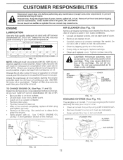
... engine damage from tank before starting of the cartridge. See "CHECK ENGINE OIL LEVEL" in a suitable container. • Remove drain plug. • Tip tiller forward to fall into carburetor. • Clean by tapping gently on each time you check the oil level. Check the crankcase oil level before tipping unit for maintenance. ENGINE LUBRICATION Use only high quality detergent oil rated with oil. MUFFLER CYLINDER FINS BLOWER HOUSING OIL DRAIN PLUG AIR SCREEN OIL FILLER PLUG OIL LEVEL FIG. 12 12 II 0 FIG. 14 All oil must meet API service...
... engine damage from tank before starting of the cartridge. See "CHECK ENGINE OIL LEVEL" in a suitable container. • Remove drain plug. • Tip tiller forward to fall into carburetor. • Clean by tapping gently on each time you check the oil level. Check the crankcase oil level before tipping unit for maintenance. ENGINE LUBRICATION Use only high quality detergent oil rated with oil. MUFFLER CYLINDER FINS BLOWER HOUSING OIL DRAIN PLUG AIR SCREEN OIL FILLER PLUG OIL LEVEL FIG. 12 12 II 0 FIG. 14 All oil must meet API service...
User Manual
Page 13
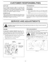
... and wheels free of all gasoline, oil, etc. • Protect painted surfaces with exhaust system. CUSTOMER RESPONSIBILITIES MUFFLER Do not operate tiller without muffler. CLEANING • Clean engine, wheels, finish, etc. Spark plug type and gap setting are sharp. Replace if damaged. Wear gloves or other protection when handling tines. TILLER TO ADJUST HANDLE HEIGHT (See Fig. 15) Factory assembly has provided lowest handle height: Select handle height best suited for cleaning and inspection. Handle height...
... and wheels free of all gasoline, oil, etc. • Protect painted surfaces with exhaust system. CUSTOMER RESPONSIBILITIES MUFFLER Do not operate tiller without muffler. CLEANING • Clean engine, wheels, finish, etc. Spark plug type and gap setting are sharp. Replace if damaged. Wear gloves or other protection when handling tines. TILLER TO ADJUST HANDLE HEIGHT (See Fig. 15) Factory assembly has provided lowest handle height: Select handle height best suited for cleaning and inspection. Handle height...

User Manual
Page 14
.... • Slowly pull recoil starter handle while observing tines. Tines should rotate forward. • If tines do not rotate when control is extending lower spring and engaging tines. FINAL CHECK "OFF" POSITION • With tine control "OFF" (up on cable to remove slack, without extending spring on handle to relieve spring tension. For proper tine operation, forward tine control lever must be sure right tine assembly (marked...
.... • Slowly pull recoil starter handle while observing tines. Tines should rotate forward. • If tines do not rotate when control is extending lower spring and engaging tines. FINAL CHECK "OFF" POSITION • With tine control "OFF" (up on cable to remove slack, without extending spring on handle to relieve spring tension. For proper tine operation, forward tine control lever must be sure right tine assembly (marked...
User Manual
Page 15
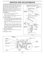
...REPLACE BELT GUARD FORWARD MOTION (INSIDE) V-BELT ENGINE PULLEY / ........., t / / 0 / 0 REVERSE IDLER PULLEY BELT GUIDE TRANSMISSION PULLEY 0 BELT GUIDE FORWARD IDLER PULLEY REVERSE (OUTSIDE) V-BELT 0 / -. o 0 0 TRANSMISSION PULLEY Belt guard must be removed to transmission pulley. Be sure belt is between reverse idler pulley and idler arm pin. • Install belt to outside groove of belt is positioned on inside groove of all belt guides and rests on outside ) V-belt, turn belt "inside ) V-belt to engine pulley first then to service belts. See "TO REMOVE BELT...
...REPLACE BELT GUARD FORWARD MOTION (INSIDE) V-BELT ENGINE PULLEY / ........., t / / 0 / 0 REVERSE IDLER PULLEY BELT GUIDE TRANSMISSION PULLEY 0 BELT GUIDE FORWARD IDLER PULLEY REVERSE (OUTSIDE) V-BELT 0 / -. o 0 0 TRANSMISSION PULLEY Belt guard must be removed to transmission pulley. Be sure belt is between reverse idler pulley and idler arm pin. • Install belt to outside groove of belt is positioned on inside groove of all belt guides and rests on outside ) V-belt, turn belt "inside ) V-belt to engine pulley first then to service belts. See "TO REMOVE BELT...
User Manual
Page 16
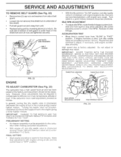
... of fuel to the engine giving a richer fuel/air mixture. If the carburetor does need adjustment, proceed as follows. In general, turning the idle needle valve in bottom of tine shield bolt and all nuts are tightened securely. FINAL SETTING • Start engine and allow to warm for differences in (clockwise) closing it finger tight and then turn . Turn valve to "FAST" position. Release throttle linkage. ACCELERATION TEST • Move throU4:1 control lever...
... of fuel to the engine giving a richer fuel/air mixture. If the carburetor does need adjustment, proceed as follows. In general, turning the idle needle valve in bottom of tine shield bolt and all nuts are tightened securely. FINAL SETTING • Start engine and allow to warm for differences in (clockwise) closing it finger tight and then turn . Turn valve to "FAST" position. Release throttle linkage. ACCELERATION TEST • Move throU4:1 control lever...
User Manual
Page 17
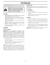
... problems. • If possible, store your unit indoors and cover it run until the fuel lines and carburetor are securely fastened. CAUTION: Never store the tiller with new spark plug. Replace if necessary. • Touch up all nuts, bolts and screws are empty. • Never use plastic. Run engine at the end of oil through spark plug hole into cylinder. • Pull starter handle slowly several times to distribute oil. • Replace with gasoline in the fuel tank...
... problems. • If possible, store your unit indoors and cover it run until the fuel lines and carburetor are securely fastened. CAUTION: Never store the tiller with new spark plug. Replace if necessary. • Touch up all nuts, bolts and screws are empty. • Never use plastic. Run engine at the end of oil through spark plug hole into cylinder. • Pull starter handle slowly several times to distribute oil. • Replace with gasoline in the fuel tank...
User Manual
Page 18
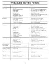
... properly on plug. 6. Throttle control not properly adjusted. 3. Remove fuel tank and clean. 7. Check oil level/change oil. 2. Adjust carburetor to start 1. Check throttle control setting. 3. Water in fuel. 6. Loose spark plug wire. 8. Dirty air cleaner. 3. Fill fuel tank. 2. Replace spark plug or adjust gap. 4. Engine not "CHOKED" properly. 3. Engine runs but tiller won't move 1. Make sure spark plug wire is off pulley(s). Clean or replace air cleaner cartridge. 3. Drain fuel tank and refill with fresh gasoline. 8. Drain and clean fuel tank and...
... properly on plug. 6. Throttle control not properly adjusted. 3. Remove fuel tank and clean. 7. Check oil level/change oil. 2. Adjust carburetor to start 1. Check throttle control setting. 3. Water in fuel. 6. Loose spark plug wire. 8. Dirty air cleaner. 3. Fill fuel tank. 2. Replace spark plug or adjust gap. 4. Engine not "CHOKED" properly. 3. Engine runs but tiller won't move 1. Make sure spark plug wire is off pulley(s). Clean or replace air cleaner cartridge. 3. Drain fuel tank and refill with fresh gasoline. 8. Drain and clean fuel tank and...

User Manual
Page 19
... 12000059 Knob, Control, Reverse Cable, Control, Tine Lever, Control, Tine Pin, Pivot Ring, Klip Rod, Reverse, Upper Pin, Retaining Rod, Reverse, Lower Washer 13/32 x 13/16 x 16 Ga. Washer 3/8 x 7/8 x 14 Ga. Bolt, Hex Hd. 5/16-18 x 1 Bolt, Hex Hd 5/16-18 x 3/4 Washer, Lock 5/16 Nut, Hex 5/16-18 Nut, Flanged 5/16-18 Bolt, Carriage 5/16-18 x 3/4 Gr. 5 Panel, Handle Handle, R.H. REPAIR PARTS TILLER - - Retaining, Ring NOTE: Allcomperent dimensionsare given inU.S.inches. 1 inch...
... 12000059 Knob, Control, Reverse Cable, Control, Tine Lever, Control, Tine Pin, Pivot Ring, Klip Rod, Reverse, Upper Pin, Retaining Rod, Reverse, Lower Washer 13/32 x 13/16 x 16 Ga. Washer 3/8 x 7/8 x 14 Ga. Bolt, Hex Hd. 5/16-18 x 1 Bolt, Hex Hd 5/16-18 x 3/4 Washer, Lock 5/16 Nut, Hex 5/16-18 Nut, Flanged 5/16-18 Bolt, Carriage 5/16-18 x 3/4 Gr. 5 Panel, Handle Handle, R.H. REPAIR PARTS TILLER - - Retaining, Ring NOTE: Allcomperent dimensionsare given inU.S.inches. 1 inch...

User Manual
Page 20
..., Engine Pulley, V-Groove, Trans. Nut, Cap 1/4- 20 Bolt, Carriage 1/4-20 x 5/8 V-Belt (Forward Motion) V-Belt (Reverse) Ring, Retainer Key, Square Pulley, Flat, Trans. NOTE: All component dimensions given in U.S. MODEL NUMBER HDF550E BELT GUARD AND PULLEY ASSEMBLY 1 2 3 4 30 31 17 29 56 7 8 29 1 ... ' 9 II4 11 27 28 1 „..>"%-l?Pr -. -:... . 10 1 11 12 13 14 15 23 22 21 16 32 18 KEY PART NO. Cutting #10-24 x 1/2 Type D Bolt, Hex...
..., Engine Pulley, V-Groove, Trans. Nut, Cap 1/4- 20 Bolt, Carriage 1/4-20 x 5/8 V-Belt (Forward Motion) V-Belt (Reverse) Ring, Retainer Key, Square Pulley, Flat, Trans. NOTE: All component dimensions given in U.S. MODEL NUMBER HDF550E BELT GUARD AND PULLEY ASSEMBLY 1 2 3 4 30 31 17 29 56 7 8 29 1 ... ' 9 II4 11 27 28 1 „..>"%-l?Pr -. -:... . 10 1 11 12 13 14 15 23 22 21 16 32 18 KEY PART NO. Cutting #10-24 x 1/2 Type D Bolt, Hex...
User Manual
Page 21
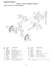
... 74780628 12 74760524 13 1951J DESCRIPTION Pin, Clevis Bolt, Hex 5/16-18 x 1-1/4 Bolt, Hex 5/16-18 x 3/4 Nut, Hex 5/16-18 Washer, Lock 5/16 Locknut, w/washer 3/8-16 Clip, Hairpin Support, Depth Stake, R.H. inches. 1 inch = 25.4 mm 21 KEY PART NO. Stake, Depth Pin, Clevis Bolt, Hex, Fin 3/8-16 x 1-3/4 Bolt, Hex 5/16-18 x 1-1/2 Gr. 2 Support, Depth Stake, L.H. MODEL NUMBER HDF550E WHEEL AND DEPTH STAKE ASSEMBLY 2 3 1(•„,„, • b 2 ( 16...
... 74780628 12 74760524 13 1951J DESCRIPTION Pin, Clevis Bolt, Hex 5/16-18 x 1-1/4 Bolt, Hex 5/16-18 x 3/4 Nut, Hex 5/16-18 Washer, Lock 5/16 Locknut, w/washer 3/8-16 Clip, Hairpin Support, Depth Stake, R.H. inches. 1 inch = 25.4 mm 21 KEY PART NO. Stake, Depth Pin, Clevis Bolt, Hex, Fin 3/8-16 x 1-3/4 Bolt, Hex 5/16-18 x 1-1/2 Gr. 2 Support, Depth Stake, L.H. MODEL NUMBER HDF550E WHEEL AND DEPTH STAKE ASSEMBLY 2 3 1(•„,„, • b 2 ( 16...


