
User Manual
Page 1
HDF550D 5 HP 24 Inch Tiller • Assembly Operation • Customer Responsibilities • Service and Adjustments Storage • Troubleshooting • Repair Parts For Parts and Service, contact our authorized distributor: call 1-800-849-1297 For Technical Assistance: call 1-800-829-5886 156332 11.3.96 TR PRINTED IN U.S.A.. OWNER'S MANUAL MODEL NO.
HDF550D 5 HP 24 Inch Tiller • Assembly Operation • Customer Responsibilities • Service and Adjustments Storage • Troubleshooting • Repair Parts For Parts and Service, contact our authorized distributor: call 1-800-849-1297 For Technical Assistance: call 1-800-829-5886 156332 11.3.96 TR PRINTED IN U.S.A.. OWNER'S MANUAL MODEL NO.
User Manual
Page 2
... INFORMATION IN THIS MANUAL. Allow the engine to cool before storing in safe working condition. • Check shear pins, engine mounting bolts, and other bolts at high speeds on slippery surfaces. • Handle fuel with the controls and the proper use care when backing. • Never allow bystanders near or under rotating parts. • Exercise extreme caution when operating on electric motors. • Do not run the engine indoors; SAFETY...
... INFORMATION IN THIS MANUAL. Allow the engine to cool before storing in safe working condition. • Check shear pins, engine mounting bolts, and other bolts at high speeds on slippery surfaces. • Handle fuel with the controls and the proper use care when backing. • Never allow bystanders near or under rotating parts. • Exercise extreme caution when operating on electric motors. • Do not run the engine indoors; SAFETY...
User Manual
Page 3
Should you experience any part which has been subjected to alteration, misuse. We have been properly assembled, adjusted, operated, and maintained in maintaining, caring for replacement under this Owner's Manual. MODEL NUMBER HDF550D SERIAL NUMBER DATE OF PURCHASE THE MODEL AND SERIAL NUMBERS WILL BE FOUND ON THE MODEL PLATE ATTACHED TO THE RIGHT HAND ENGINE BRACKET. YOU SHOULD RECORD BOTH SERIAL NUMBER AND DATE OF PURCHASE AND KEEP IN A SAFE...
Should you experience any part which has been subjected to alteration, misuse. We have been properly assembled, adjusted, operated, and maintained in maintaining, caring for replacement under this Owner's Manual. MODEL NUMBER HDF550D SERIAL NUMBER DATE OF PURCHASE THE MODEL AND SERIAL NUMBERS WILL BE FOUND ON THE MODEL PLATE ATTACHED TO THE RIGHT HAND ENGINE BRACKET. YOU SHOULD RECORD BOTH SERIAL NUMBER AND DATE OF PURCHASE AND KEEP IN A SAFE...
User Manual
Page 4
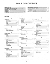
... PRODUCT SPECIFICATIONS WARRANTY ASSEMBLY OPERATION 2 3, 11-13 3 3 5-6 7=10 MAINTENANCE SCHEDULE SERVICE .& ADJUSTMENTS STORAGE TROUBLESHOOTING REPAIR PARTS-TILLER 11 13=16 17 18 19-24 INDEX A Adjustments: Carburetor Depth Stake Handle Height Tines V-Belt Wheels Air Cleaner. Belt, V-: Belt Guard Repair Parts V-Belt Replacement Cdoling System Controls: Choke Throttle Tines Cultivating Customer Responsibilities: Air Cleaner.. Service & Adjustments: Carburetor Handle Height. Tines V-Belt Wheels Service: Repair Parts Service Record Spark Plug: Gap Maintenance Storage...
... PRODUCT SPECIFICATIONS WARRANTY ASSEMBLY OPERATION 2 3, 11-13 3 3 5-6 7=10 MAINTENANCE SCHEDULE SERVICE .& ADJUSTMENTS STORAGE TROUBLESHOOTING REPAIR PARTS-TILLER 11 13=16 17 18 19-24 INDEX A Adjustments: Carburetor Depth Stake Handle Height Tines V-Belt Wheels Air Cleaner. Belt, V-: Belt Guard Repair Parts V-Belt Replacement Cdoling System Controls: Choke Throttle Tines Cultivating Customer Responsibilities: Air Cleaner.. Service & Adjustments: Carburetor Handle Height. Tines V-Belt Wheels Service: Repair Parts Service Record Spark Plug: Gap Maintenance Storage...
User Manual
Page 6
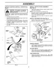
... pin. LOCK NUT WASHER TILLER HANDLE HANDLE PANEL a FLAT WASHER HEX BOLT 5/16-18X1" HEX BOLT 5/16-18X3/4" CABLE TILLER HANDLES HANDLE PAN EL BOLTS 0 UPPER REVERSE ROD COTTER PIN O CLEWS PIN INSTALL DEPTH STAKE ASSEMBLY (See Fig. 3) • Insert stake support between engine bracket halves with handle panel hole and slot. • Loosely assemble hardware as shown. Be sure the shorter (3/4" long) hex bolt is assembled in the Service and Adjustments section of this manual...
... pin. LOCK NUT WASHER TILLER HANDLE HANDLE PANEL a FLAT WASHER HEX BOLT 5/16-18X1" HEX BOLT 5/16-18X3/4" CABLE TILLER HANDLES HANDLE PAN EL BOLTS 0 UPPER REVERSE ROD COTTER PIN O CLEWS PIN INSTALL DEPTH STAKE ASSEMBLY (See Fig. 3) • Insert stake support between engine bracket halves with handle panel hole and slot. • Loosely assemble hardware as shown. Be sure the shorter (3/4" long) hex bolt is assembled in the Service and Adjustments section of this manual...

User Manual
Page 7
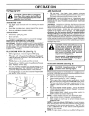
.... CHOKE CONTROL - Controls forward speed and the depth at which the tiller will dig. Compare the illustrations with your Tiller or in literature supplied with the location of the American National Standards Institute. These symbols may appear on your tiller to start the engine. 7 Engages tines in forward direction. RECOIL STARTER HANDLE - Used to familiarize yourself with the product. OPERATION KNOW YOUR TILLER READ THIS OWNER'S MANUAL...
.... CHOKE CONTROL - Controls forward speed and the depth at which the tiller will dig. Compare the illustrations with your Tiller or in literature supplied with the location of the American National Standards Institute. These symbols may appear on your tiller to start the engine. 7 Engages tines in forward direction. RECOIL STARTER HANDLE - Used to familiarize yourself with the product. OPERATION KNOW YOUR TILLER READ THIS OWNER'S MANUAL...

User Manual
Page 8
.... HOW TO USE YOUR TILLER Know how to start engine. Replace the hairpin clip and clevis pin. • For normal tilling, set depth stake at the second or third hole from the top. Always wear safety glasses or eye shields before adding fuel and oil or attempting to operate all controls before starting your tiller and while tilling. Change wheel position. WHEELS (See Fig. 6) Adjust wheels by removing the hairpin...
.... HOW TO USE YOUR TILLER Know how to start engine. Replace the hairpin clip and clevis pin. • For normal tilling, set depth stake at the second or third hole from the top. Always wear safety glasses or eye shields before adding fuel and oil or attempting to operate all controls before starting your tiller and while tilling. Change wheel position. WHEELS (See Fig. 6) Adjust wheels by removing the hairpin...
User Manual
Page 9
... section of this manual). Never use gasoline near an open flame. • Check oil level. For approximate capacity see troubleshooting points. 9 Refill to desired running position. NOTE: A warm engine requires less choking to start the engine and let it is held by the stake spring. • Push tiller handles down, raising tines off any source of overflowing if necessary. Disconnect spark plug wire. Drain the gas tank, start . • Move throttle control to point of...
... section of this manual). Never use gasoline near an open flame. • Check oil level. For approximate capacity see troubleshooting points. 9 Refill to desired running position. NOTE: A warm engine requires less choking to start the engine and let it is held by the stake spring. • Push tiller handles down, raising tines off any source of overflowing if necessary. Disconnect spark plug wire. Drain the gas tank, start . • Move throttle control to point of...
User Manual
Page 10
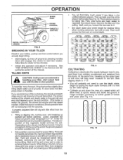
... minutes. • Check tine operation and adjust if necessary. doing this vegetable matter enriches the soil.. OPERATION SPARK PLUG CHOKE CONTROL. A 31 Jr A,. THROTTLE CONTROL II RECOIL STARTER HANDLE FIG. 8 BREAKING IN YOUR TILLER Break-in rough condition, promoting no further growth of the wheels and depth stake is 4"-6". TILLING HINTS a CAUTION: Untilyouare accustomed to uproot weeds* and leave the ground in your tiller. turning over the...
... minutes. • Check tine operation and adjust if necessary. doing this vegetable matter enriches the soil.. OPERATION SPARK PLUG CHOKE CONTROL. A 31 Jr A,. THROTTLE CONTROL II RECOIL STARTER HANDLE FIG. 8 BREAKING IN YOUR TILLER Break-in rough condition, promoting no further growth of the wheels and depth stake is 4"-6". TILLING HINTS a CAUTION: Untilyouare accustomed to uproot weeds* and leave the ground in your tiller. turning over the...
User Manual
Page 11
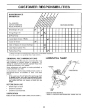
CUSTOMER RESPONSIBILITIES MAINTENANCE SCHEDULE 4, co co co •z• c'' o o FILL IN DATES AS YOU COMPLETE REGULAR SERVICE Check Engine Oil Level 0 'e A. 03 4- -I.cii -1.
CUSTOMER RESPONSIBILITIES MAINTENANCE SCHEDULE 4, co co co •z• c'' o o FILL IN DATES AS YOU COMPLETE REGULAR SERVICE Check Engine Oil Level 0 'e A. 03 4- -I.cii -1.
User Manual
Page 12
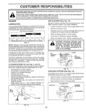
... result in a suitable container. • Remove drain plug. • Tip tiller forward to prevent accidental starting of the cartridge. For proper engine performance and long life keep your engine clean. • Clean air screen frequently using a stiff-bristled brush. • Remove blower housing and clean as kerosene, are not to be used to clean cartridge. Check the crankcase oil level before performing any maintenance (except carburetor adjustment) to drain oil. AIR CLEANER SCREW COVER AIR CLEANER CARTRIDGE FIG. 13 COOLING SYSTEM...
... result in a suitable container. • Remove drain plug. • Tip tiller forward to prevent accidental starting of the cartridge. For proper engine performance and long life keep your engine clean. • Clean air screen frequently using a stiff-bristled brush. • Remove blower housing and clean as kerosene, are not to be used to clean cartridge. Check the crankcase oil level before performing any maintenance (except carburetor adjustment) to drain oil. AIR CLEANER SCREW COVER AIR CLEANER CARTRIDGE FIG. 13 COOLING SYSTEM...
User Manual
Page 13
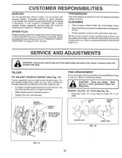
... shaft. CLEVIS PIN OUTER TINE I 01 HAIRPIN CLIP FIG. 16 INNER TINE FIG. 15 13 CLEANING • Clean engine, wheels, finish, etc. Spark plug type and gap setting are shown in several different ways to keep water out. Keep finished surfaces and wheels free of this manual. We do not recommend using a garden hose to desired location. • Tighten the four nuts securely. SERVICE AND ADJUSTMENTS a CAUTION: Disconnect spark plug wire from spark plug...
... shaft. CLEVIS PIN OUTER TINE I 01 HAIRPIN CLIP FIG. 16 INNER TINE FIG. 15 13 CLEANING • Clean engine, wheels, finish, etc. Spark plug type and gap setting are shown in several different ways to keep water out. Keep finished surfaces and wheels free of this manual. We do not recommend using a garden hose to desired location. • Tighten the four nuts securely. SERVICE AND ADJUSTMENTS a CAUTION: Disconnect spark plug wire from spark plug...

User Manual
Page 14
... ground. • Slowly pull recoil starter handle while observing tines. Loosen cable clip and pull cable up to remove slack and retighten clip. • Recheck in "OFF" position and adjust if necessary. 14 BO •Y TINE CONTROL "ON" POSITION CABLE CLIP TINE CONTROL CABLE a, 0 0 FIG. 19 TINE OPERATION CHECK (See Fig. 19) a WARNING: Disconnect spark plug wire from inner wire of control cable is too tight which is in tine shaft. 0 0 FIG. 17...
... ground. • Slowly pull recoil starter handle while observing tines. Loosen cable clip and pull cable up to remove slack and retighten clip. • Recheck in "OFF" position and adjust if necessary. 14 BO •Y TINE CONTROL "ON" POSITION CABLE CLIP TINE CONTROL CABLE a, 0 0 FIG. 19 TINE OPERATION CHECK (See Fig. 19) a WARNING: Disconnect spark plug wire from inner wire of control cable is too tight which is in tine shaft. 0 0 FIG. 17...
User Manual
Page 15
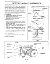
... positioned on idler pulley. • Before installing reverse (outside) V-belt, turn belt "inside ) and reverse (outside groove of engine pulley. IDLER ARM PIN Il ENGINE PULLEY 115- III REVERSE IDLER PULLEY IDLER ARM PIN REVERSE IDLER ARM FORWARD MOTION (INSIDE) V-BELT ENGINE PULLEY BELT GUIDE a, (Zi FOR ARD IDLER PULLEY FIG. 20 15 FIG. 21 REVERSE (OUTSIDE) V-BELT BELT GUARD BOLT ( TRANSMISSION PULLEY BELT REMOVAL • Remove reverse idler pulley from idler arm. • Remove reverse (outside groove of transmission pulley. BELT REPLACEMENT • Install new...
... positioned on idler pulley. • Before installing reverse (outside) V-belt, turn belt "inside ) and reverse (outside groove of engine pulley. IDLER ARM PIN Il ENGINE PULLEY 115- III REVERSE IDLER PULLEY IDLER ARM PIN REVERSE IDLER ARM FORWARD MOTION (INSIDE) V-BELT ENGINE PULLEY BELT GUIDE a, (Zi FOR ARD IDLER PULLEY FIG. 20 15 FIG. 21 REVERSE (OUTSIDE) V-BELT BELT GUARD BOLT ( TRANSMISSION PULLEY BELT REMOVAL • Remove reverse idler pulley from idler arm. • Remove reverse (outside groove of transmission pulley. BELT REPLACEMENT • Install new...

User Manual
Page 16
...; With throttle control in "SLOW" position, turn idle needle valve in (clockwise) closing it finger tight and then turn . Turning the needle valve out (counterclockwise) increases the supply of fuel to the engine giving a leaner fuel/air mixture. FINAL SETTING • Start engine and allow to warm for differences in bottom of belt guard is factory adjusted. ACCELERATION TEST • Move throttle control lever from unit. • Replace belt guard by reversing above procedure. SERVICE AND ADJUSTMENTS TO REMOVE BELT GUARD...
...; With throttle control in "SLOW" position, turn idle needle valve in (clockwise) closing it finger tight and then turn . Turning the needle valve out (counterclockwise) increases the supply of fuel to the engine giving a leaner fuel/air mixture. FINAL SETTING • Start engine and allow to warm for differences in bottom of belt guard is factory adjusted. ACCELERATION TEST • Move throttle control lever from unit. • Replace belt guard by reversing above procedure. SERVICE AND ADJUSTMENTS TO REMOVE BELT GUARD...
User Manual
Page 17
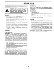
... the formation of oil through spark plug hole into cylinder. • Pull starter handle slowly several times to distribute oil. • Replace with a suitable protective cover that all rusted or chipped paint surfaces; CYLINDERS • Remove spark plug. • Pour 1 ounce (29 ml) of fuel gum deposits during storage. Do not use engine or carburetor cleaner products in any enclosure. Do not drain the gas tank and carburetor if using fuel stabilizer. OTHER...
... the formation of oil through spark plug hole into cylinder. • Pull starter handle slowly several times to distribute oil. • Replace with a suitable protective cover that all rusted or chipped paint surfaces; CYLINDERS • Remove spark plug. • Pour 1 ounce (29 ml) of fuel gum deposits during storage. Do not use engine or carburetor cleaner products in any enclosure. Do not drain the gas tank and carburetor if using fuel stabilizer. OTHER...
User Manual
Page 18
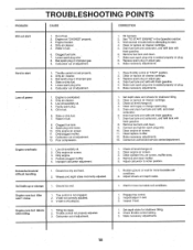
... spark plug or adjust gap. 4. Drain fuel tank and refill with fresh gasoline. 8. Out of power 1. Dirty air cleaner. 3. Engine overheats 1. Dirty engine air screen. 3. Dirty engine. 4. Carburetor out of adjustment. Clean or replace air cleaner cartridge. 3. Moisten ground or wait for shallower tilling. 2. Inspect/adjust V-belt. 3. Check oil level/change spark plug. 5. Improper carburetor adjustment. Dirty air cleaner. 5. Carburetor out of adjustment. 1. Tine control is not engaged. 2. Tilling too deep. 2. Check oil level/change oil. • 2. TROUBLESHOOTING...
... spark plug or adjust gap. 4. Drain fuel tank and refill with fresh gasoline. 8. Out of power 1. Dirty air cleaner. 3. Engine overheats 1. Dirty engine air screen. 3. Dirty engine. 4. Carburetor out of adjustment. Clean or replace air cleaner cartridge. 3. Moisten ground or wait for shallower tilling. 2. Inspect/adjust V-belt. 3. Check oil level/change spark plug. 5. Improper carburetor adjustment. Dirty air cleaner. 5. Carburetor out of adjustment. 1. Tine control is not engaged. 2. Tilling too deep. 2. Check oil level/change oil. • 2. TROUBLESHOOTING...

User Manual
Page 19
... MODEL NUMBER HDF550D HANDLE ASSEMBLY 19 16 2 3 4 28 11 10 11-20 2141,--29 -- „ /, • /7/ / 1/ 22 7 8 27 , ; DESCRIPTION 1 131268X428 Bracket,•Handie 2 72140512 Bolt; DESCRIPTION 17 106932X 18 3066J 19 151229 20 154805 21 12000027 22 101248K 23 1778E 24 2613J 25 1913/316 26 76020412 27 76020308 28 19131312 29 12000059 Knob, Control, Reverse Cable, Control, Tine Lever, Control, Tine Pin...
... MODEL NUMBER HDF550D HANDLE ASSEMBLY 19 16 2 3 4 28 11 10 11-20 2141,--29 -- „ /, • /7/ / 1/ 22 7 8 27 , ; DESCRIPTION 1 131268X428 Bracket,•Handie 2 72140512 Bolt; DESCRIPTION 17 106932X 18 3066J 19 151229 20 154805 21 12000027 22 101248K 23 1778E 24 2613J 25 1913/316 26 76020412 27 76020308 28 19131312 29 12000059 Knob, Control, Reverse Cable, Control, Tine Lever, Control, Tine Pin...

User Manual
Page 20
..., Idler Bolt, Hex 3/8-16 x 1-1/4 Shaft, Idler Arm Nut, Hex, Jam 5/16-18 Nut, Fin Hex 1/4-20 Washer LK Hvy Helical 1/4 Pad, Idler Screw, Set , Socket, Headless C.P. 1/4-20 x 1 /4 Sheave, Engine Pulley, V-Groove, Trans. MODEL NUMBER HDF550D BELT GUARD AND PULLEY ASSEMBLY 2 3 4 5g 7 8 29 11 .....-- 30 31 17 -„. -.....v....,..>„ 29 -4,3 s.. •%., 9 11 ' 27 28 / 19 10 J 1 12 13 14 15 ( 24 23 22 21 KEY PART NO...
..., Idler Bolt, Hex 3/8-16 x 1-1/4 Shaft, Idler Arm Nut, Hex, Jam 5/16-18 Nut, Fin Hex 1/4-20 Washer LK Hvy Helical 1/4 Pad, Idler Screw, Set , Socket, Headless C.P. 1/4-20 x 1 /4 Sheave, Engine Pulley, V-Groove, Trans. MODEL NUMBER HDF550D BELT GUARD AND PULLEY ASSEMBLY 2 3 4 5g 7 8 29 11 .....-- 30 31 17 -„. -.....v....,..>„ 29 -4,3 s.. •%., 9 11 ' 27 28 / 19 10 J 1 12 13 14 15 ( 24 23 22 21 KEY PART NO...
User Manual
Page 21
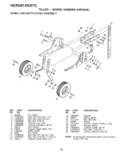
MODEL NUMBER HDF550D WHEEL AND DEPTH STAKE ASSEMBLY 16 17 2 21 18 9 20 22 2 3 ' -tr .7.1"7r-, ,,,;. / I ii lil 1 / /13/ e; 1s> JS ,.-' - // ,./ 1....,01-t 13_,.a(..., 14 7 9 8 0 10 0 • fif 11 12 REPAIR PARTS TILLER - -
MODEL NUMBER HDF550D WHEEL AND DEPTH STAKE ASSEMBLY 16 17 2 21 18 9 20 22 2 3 ' -tr .7.1"7r-, ,,,;. / I ii lil 1 / /13/ e; 1s> JS ,.-' - // ,./ 1....,01-t 13_,.a(..., 14 7 9 8 0 10 0 • fif 11 12 REPAIR PARTS TILLER - -


