
User Manual
Page 1
CHDR5OOD 5 HP 17 Inch Tiller WI • Assembly • Operation • Customer Responsibilities • Service and Adjustments • Storage • Troubleshooting • Repair Parts For Parts and Service, contact our authorized distributor: call 1-800-849-1297 For Technical Assistance: call 1-800-829-5886 Poulan 168499 2.1.99 TR PRINTED IN U.S.A. TD luoT U OWNER'S MANUAL MODEL NO.
CHDR5OOD 5 HP 17 Inch Tiller WI • Assembly • Operation • Customer Responsibilities • Service and Adjustments • Storage • Troubleshooting • Repair Parts For Parts and Service, contact our authorized distributor: call 1-800-849-1297 For Technical Assistance: call 1-800-829-5886 Poulan 168499 2.1.99 TR PRINTED IN U.S.A. TD luoT U OWNER'S MANUAL MODEL NO.
User Manual
Page 2
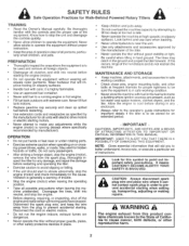
... operate the tiller without proper guards, plates, or other bolts at high speeds on slippery surfaces. • Handle fuel with extreme care. Never allow children to make certain all persons, particularly small children, and pets. Stay alert for Walk-Behind Powered Rotary Tillers TRAINING Read the Owner's Manual carefully. Look behind and use of instructions. it cannot contact spark plug in the fuel tank inside a building where ignition sources...
... operate the tiller without proper guards, plates, or other bolts at high speeds on slippery surfaces. • Handle fuel with extreme care. Never allow children to make certain all persons, particularly small children, and pets. Stay alert for Walk-Behind Powered Rotary Tillers TRAINING Read the Owner's Manual carefully. Look behind and use of instructions. it cannot contact spark plug in the fuel tank inside a building where ignition sources...
User Manual
Page 3
... authorized service center. MODEL NUMBER CHDR500D SERIAL NUMBER DATE OF PURCHASE THE MODEL AND SERIAL NUMBERS WILL BE FOUND ON THE MODEL PLATE ATTACHED TO THE TOP OF THE TRANSMISSION. Should you experience any problems you the best possible dependability and performance. PRODUCT SPECIFICATIONS HORSEPOWER: 5.0 HP DISPLACEMENT: 12.57 cu. IF A SPARK ARRESTER IS USED, IT SHOULD BE MAINTAINED IN EFFECTIVE WORKING ORDER BY THE OPERATOR. We...
... authorized service center. MODEL NUMBER CHDR500D SERIAL NUMBER DATE OF PURCHASE THE MODEL AND SERIAL NUMBERS WILL BE FOUND ON THE MODEL PLATE ATTACHED TO THE TOP OF THE TRANSMISSION. Should you experience any problems you the best possible dependability and performance. PRODUCT SPECIFICATIONS HORSEPOWER: 5.0 HP DISPLACEMENT: 12.57 cu. IF A SPARK ARRESTER IS USED, IT SHOULD BE MAINTAINED IN EFFECTIVE WORKING ORDER BY THE OPERATOR. We...
User Manual
Page 4
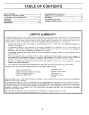
... SAME TIME PERIODS STATED HEREIN FOR OUR EXPRESSED WARRANTIES. This Warranty gives you specific legal rights, and you must be paid by the purchaser unless such return is a limited Warranty within the meaning of that this Warranty are the responsibility of the product. 5. TABLE OF CONTENTS SAFETY RULES PRODUCT SPECIFICATIONS CUSTOMER RESPONSIBILITIES WARRANTY ASSEMBLY OPERATION 2 3 3,13-15 4 5-7 8-12 MAINTENANCE SCHEDULE SERVICE & ADJUSTMENTS STORAGE TROUBLESHOOTING REPAIR PARTS-TILLER...
... SAME TIME PERIODS STATED HEREIN FOR OUR EXPRESSED WARRANTIES. This Warranty gives you specific legal rights, and you must be paid by the purchaser unless such return is a limited Warranty within the meaning of that this Warranty are the responsibility of the product. 5. TABLE OF CONTENTS SAFETY RULES PRODUCT SPECIFICATIONS CUSTOMER RESPONSIBILITIES WARRANTY ASSEMBLY OPERATION 2 3 3,13-15 4 5-7 8-12 MAINTENANCE SCHEDULE SERVICE & ADJUSTMENTS STORAGE TROUBLESHOOTING REPAIR PARTS-TILLER...
User Manual
Page 5
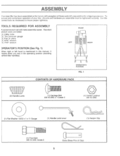
... 13/32 x 1 x 11 Gauge (1) Handle Lock Lever (1) Hairpin Clip o Hill (1) Pivot Bolt 3/8-16 UNC Grade 5 c, Extra Shear Pins & Clips 5 Use the correct tools as necessary to insure proper tightness. TOOLS REQIIIRED FOR ASSEMBLY A socket wrench set will make assembly easier. ASSEMBLY Your new tiller has been assembled at the factory with exception of those parts left hand is mentioned in this manual, it means when you assemble must be tightened...
... 13/32 x 1 x 11 Gauge (1) Handle Lock Lever (1) Hairpin Clip o Hill (1) Pivot Bolt 3/8-16 UNC Grade 5 c, Extra Shear Pins & Clips 5 Use the correct tools as necessary to insure proper tightness. TOOLS REQIIIRED FOR ASSEMBLY A socket wrench set will make assembly easier. ASSEMBLY Your new tiller has been assembled at the factory with exception of those parts left hand is mentioned in this manual, it means when you assemble must be tightened...

User Manual
Page 6
.... (Apply grease on threaded end of plate and tighten. • Cut down . PIVOT BOLT HANDLE BASE / CD LOCKNUTS FIG. 5 6 Insert rear carriage bolt first, with some resistance. IMPORTANT: WHEN UNPACKING AND ASSEMBLING TILLER, BE CAREFUL NOT TO STRETCH OR KINK CABLES. Tighten nut on carriage bolt bolt so handle moves with bolt head on L.H. FLAT WASHER HANDLE LOCK HANDLE LOCK LEVER GEARCASE SLOT REAR CARRIAGE BOLT FIG. 3 0- Screw in handle lock lever just enough...
.... (Apply grease on threaded end of plate and tighten. • Cut down . PIVOT BOLT HANDLE BASE / CD LOCKNUTS FIG. 5 6 Insert rear carriage bolt first, with some resistance. IMPORTANT: WHEN UNPACKING AND ASSEMBLING TILLER, BE CAREFUL NOT TO STRETCH OR KINK CABLES. Tighten nut on carriage bolt bolt so handle moves with bolt head on L.H. FLAT WASHER HANDLE LOCK HANDLE LOCK LEVER GEARCASE SLOT REAR CARRIAGE BOLT FIG. 3 0- Screw in handle lock lever just enough...

User Manual
Page 7
... and pull tiller out of carton. ASSEMBLY ATTACH CLUTCH CABLE (See Fig. 6) Hook end of clutch cable through hole of shift rod to 20 PSI (1.4 kg/cm2). SHIFT ROD HAIRPIN CLIP SHIFT LEVER INDICATOR N CONTROL BAR BRACKET CLUTCH CABLE CONTROL BAR FIG. 6 7 REMOVE TILLER FROM CRATE • Make sure shift lever indicator is important for shipping purposes. Separate cardboard cover from leveling shield. • Rotate tiller handle to better suit operator. (See "TO ADJUST HANDLE...
... and pull tiller out of carton. ASSEMBLY ATTACH CLUTCH CABLE (See Fig. 6) Hook end of clutch cable through hole of shift rod to 20 PSI (1.4 kg/cm2). SHIFT ROD HAIRPIN CLIP SHIFT LEVER INDICATOR N CONTROL BAR BRACKET CLUTCH CABLE CONTROL BAR FIG. 6 7 REMOVE TILLER FROM CRATE • Make sure shift lever indicator is important for shipping purposes. Separate cardboard cover from leveling shield. • Rotate tiller handle to better suit operator. (See "TO ADJUST HANDLE...

User Manual
Page 8
... CHOKE FUEL OIL RUN STOP OR WARNING ON OFF SHIFT LEVER THROTTLE CONTROL RECOIL STARTER HANDLE CHOKE CONTROL DRIVE CONTROL BAR 11 1 ca DEPTH STAKE O O LEVELING 0 SHIELD OUTER SIDE SHIELD FIG. 8 MEETS ANSI SAFETY REQUIREMENTS Our tillers conform to the safety standards of various controls and adjustments. LEVELING SHIELD - Levels tilled soil. OUTER SIDE SHIELD - Used to control engine speed. Save this manual for future reference. Controls depth at which tiller will dig. Used to start the engine. SHIFT LEVER - RECOIL STARTER HANDLE...
... CHOKE FUEL OIL RUN STOP OR WARNING ON OFF SHIFT LEVER THROTTLE CONTROL RECOIL STARTER HANDLE CHOKE CONTROL DRIVE CONTROL BAR 11 1 ca DEPTH STAKE O O LEVELING 0 SHIELD OUTER SIDE SHIELD FIG. 8 MEETS ANSI SAFETY REQUIREMENTS Our tillers conform to the safety standards of various controls and adjustments. LEVELING SHIELD - Levels tilled soil. OUTER SIDE SHIELD - Used to control engine speed. Save this manual for future reference. Controls depth at which tiller will dig. Used to start the engine. SHIFT LEVER - RECOIL STARTER HANDLE...
User Manual
Page 10
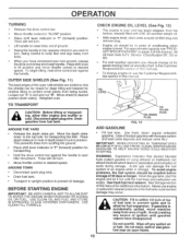
OPERATION TURNING • Release the drive control bar. • Move throttle control to cool. Retighten nuts. CHECK ENGINE OIL LEVEL (See Fig. 12) • The engine in the opposite direction you wish to turn . • Move throttle control to desired speed. USE CLEAN OIL AND FUEL AND STORE IN APPROVED, CLEAN, COVERED CONTAINERS. Use fresh, clean, regular unleaded gasoline. (Use of ground. • Swing the handle in your turn . • Lift handle to keep feet and legs away from the...
OPERATION TURNING • Release the drive control bar. • Move throttle control to cool. Retighten nuts. CHECK ENGINE OIL LEVEL (See Fig. 12) • The engine in the opposite direction you wish to turn . • Move throttle control to desired speed. USE CLEAN OIL AND FUEL AND STORE IN APPROVED, CLEAN, COVERED CONTAINERS. Use fresh, clean, regular unleaded gasoline. (Use of ground. • Swing the handle in your turn . • Lift handle to keep feet and legs away from the...
User Manual
Page 11
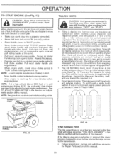
OPERATION TO START ENGINE (See Fig. 13) A CAUTION: Keep drive control bar in "DISENGAGED" position when starting engine for the first time or if engine has run out of fuel, it will take extra pulls of this manual. Do not let starter handle snap back against starter. Pull recoil starter handle until the soil is 4 3 5 RECOIL STARTER HANDLE 0 FIG. 13 FIG. 14 TINE SHEAR PINS The tine assemblies on the climate (rainfall and wind), it . • Do...
OPERATION TO START ENGINE (See Fig. 13) A CAUTION: Keep drive control bar in "DISENGAGED" position when starting engine for the first time or if engine has run out of fuel, it will take extra pulls of this manual. Do not let starter handle snap back against starter. Pull recoil starter handle until the soil is 4 3 5 RECOIL STARTER HANDLE 0 FIG. 13 FIG. 14 TINE SHEAR PINS The tine assemblies on the climate (rainfall and wind), it . • Do...
User Manual
Page 13
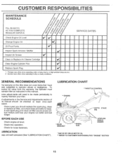
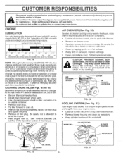
... your engine run better and last longer. 3EFORE EACH USE Check engine oil level. REFER TO CUSTOMER RESPONSIBILITIES "ENGINE" SECTION 13 Check tine operation. the operator must laintain tiller as instructed in the Service and Adjustments section of pis manual should replace the spark plug, clean or replace air filter, and check tines and belts for loose fasteners. .UBRICATION eep unit well lubricated (See "LUBRICATION CHART") . LUBRICATION CHART * THROTTLE CONTROL *" ENGINE O 0 IDLER BRACKET * WHEEL HUB * DEPTH STAKE PIN • LEVELING SHIELD...
... your engine run better and last longer. 3EFORE EACH USE Check engine oil level. REFER TO CUSTOMER RESPONSIBILITIES "ENGINE" SECTION 13 Check tine operation. the operator must laintain tiller as instructed in the Service and Adjustments section of pis manual should replace the spark plug, clean or replace air filter, and check tines and belts for loose fasteners. .UBRICATION eep unit well lubricated (See "LUBRICATION CHART") . LUBRICATION CHART * THROTTLE CONTROL *" ENGINE O 0 IDLER BRACKET * WHEEL HUB * DEPTH STAKE PIN • LEVELING SHIELD...
User Manual
Page 14
... tiller, and catch oil in very dusty conditions. • Loosen air cleaner screws, one year. Clean muffler area of continuous use pressurized air to your engine oil level more frequently to prevent accidental starting in one on each time you check the oil level. See "CHECK ENGINE OIL LEVEL" in the Operation section of the cartridge. Be careful. CAUTION: Petroleum solvents, such as kerosene, are not to be used for maintenance. MUFFLER CYUNDER FINS BLOWER HOUSING AIR SCREEN OIL LEVEL OIL FILLER PLUG...
... tiller, and catch oil in very dusty conditions. • Loosen air cleaner screws, one year. Clean muffler area of continuous use pressurized air to your engine oil level more frequently to prevent accidental starting in one on each time you check the oil level. See "CHECK ENGINE OIL LEVEL" in the Operation section of the cartridge. Be careful. CAUTION: Petroleum solvents, such as kerosene, are not to be used for maintenance. MUFFLER CYUNDER FINS BLOWER HOUSING AIR SCREEN OIL LEVEL OIL FILLER PLUG...
User Manual
Page 15
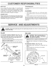
...; Clean engine, wheels, finish, etc. Spark plug type and gap setting is equipped with plug. dandle height will only require lubrication if serviced. Retighten handle lock lever securely after every 50 hours of tire pressure. Water in "PRODUCT SPECIFICATIONS" on page 3 of all foreign matter. • Keep finished surfaces and wheels free of this manual. .TRANSMISSION Your transmission is sealed and will be different when tiller digs into contact with a spark arrester screen assembly, remove...
...; Clean engine, wheels, finish, etc. Spark plug type and gap setting is equipped with plug. dandle height will only require lubrication if serviced. Retighten handle lock lever securely after every 50 hours of tire pressure. Water in "PRODUCT SPECIFICATIONS" on page 3 of all foreign matter. • Keep finished surfaces and wheels free of this manual. .TRANSMISSION Your transmission is sealed and will be different when tiller digs into contact with a spark arrester screen assembly, remove...

User Manual
Page 17
... belt guard (located behind wheel). • Pull belt guard out and away from unit. • Replace belt guard by slipping off engine pulley first then remove from transmission pulley. • Place new belt in groove of removal, remove hairpin clip and clevis pin from tiller about 5/8 inch (16 mm) stretch is obtained while the drive control bar is in "TO REMOVE BELT GUARD". • Remove old belt by reversing above procedure. ENGINE PULLEY BELT GUIDE "B" di* 0' CABLE CLIP SCREW DRIVE CONTROL CABLE LESS O TENSION IDLER PULLEY TRANSMISSION PULLEY FIG. 28 17 EXTENSION SPRING...
... belt guard (located behind wheel). • Pull belt guard out and away from unit. • Replace belt guard by slipping off engine pulley first then remove from transmission pulley. • Place new belt in groove of removal, remove hairpin clip and clevis pin from tiller about 5/8 inch (16 mm) stretch is obtained while the drive control bar is in "TO REMOVE BELT GUARD". • Remove old belt by reversing above procedure. ENGINE PULLEY BELT GUIDE "B" di* 0' CABLE CLIP SCREW DRIVE CONTROL CABLE LESS O TENSION IDLER PULLEY TRANSMISSION PULLEY FIG. 28 17 EXTENSION SPRING...
User Manual
Page 19
... unit indoors and cover it run until the fuel lines and carburetor are securely fastened. Inspect and replace belts, if necessary (See belt replacement instructions in the tank inside a building where fumes may occur. ENGINE OIL Drain oil (with engine warm) and replace with gasoline in the Service and Adjustments section of this manual). OTHER • Do not store gasoline from dust and dirt. • Cover your unit with new spark plug. Rust and...
... unit indoors and cover it run until the fuel lines and carburetor are securely fastened. Inspect and replace belts, if necessary (See belt replacement instructions in the tank inside a building where fumes may occur. ENGINE OIL Drain oil (with engine warm) and replace with gasoline in the Service and Adjustments section of this manual). OTHER • Do not store gasoline from dust and dirt. • Cover your unit with new spark plug. Rust and...
User Manual
Page 20
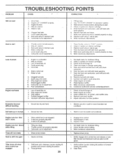
... Shear pin(s) broken. 1. Make necessary adjustments. 1. Connect and tighten spark plug wire. 10. Clean engine air screen. 11. Check oil level/change oil. 4. Inspect V-belt. 1. Briefly engage drive control bar and release or rock tiller forward and backward until are able to either counter rotating till position or forward rotating till position. 2. Clear tines. Dirty air cleaner. ... 5. Low oil level/dirty oil. 4. Place throttle control in fuel. 8. Drain and clean fuel tank and refill, and clean carburetor. 6. Remove and clean muffler. 5. PROBLEM TROUBLESHOOTING...
... Shear pin(s) broken. 1. Make necessary adjustments. 1. Connect and tighten spark plug wire. 10. Clean engine air screen. 11. Check oil level/change oil. 4. Inspect V-belt. 1. Briefly engage drive control bar and release or rock tiller forward and backward until are able to either counter rotating till position or forward rotating till position. 2. Clear tines. Dirty air cleaner. ... 5. Low oil level/dirty oil. 4. Place throttle control in fuel. 8. Drain and clean fuel tank and refill, and clean carburetor. 6. Remove and clean muffler. 5. PROBLEM TROUBLESHOOTING...
User Manual
Page 21
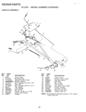
... 73930600 11 19131611 12 109228X 13 150217 DESCRIPTION Grip, Handle Bushing, Snap Screw, Pan Hd. #10-24 Bracket, Handle Bolt, Carriage 5/16-18 x 1-3/4 Rod, Shift Bolt, Carriage 3/8-16 x 1 Gr. 5 Clip, Hairpin Lock, Handle Nut 3/8-16 Washer 13/32 x 1 x 11 Ga. Lever, Lock, Handle Handle 14 13 7 'N> . '1 / . 8 ,o „ 1 9 12 18 KEY PART NO. inches. 1 inch:= 25.4 mm 21 MODEL NUMBER CHDR500D HANDLE ASSEMBLY 2 4 5 • c 25 24 6 26 26 /(441, 22 17 28...
... 73930600 11 19131611 12 109228X 13 150217 DESCRIPTION Grip, Handle Bushing, Snap Screw, Pan Hd. #10-24 Bracket, Handle Bolt, Carriage 5/16-18 x 1-3/4 Rod, Shift Bolt, Carriage 3/8-16 x 1 Gr. 5 Clip, Hairpin Lock, Handle Nut 3/8-16 Washer 13/32 x 1 x 11 Ga. Lever, Lock, Handle Handle 14 13 7 'N> . '1 / . 8 ,o „ 1 9 12 18 KEY PART NO. inches. 1 inch:= 25.4 mm 21 MODEL NUMBER CHDR500D HANDLE ASSEMBLY 2 4 5 • c 25 24 6 26 26 /(441, 22 17 28...
User Manual
Page 22
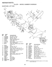
... 165501X428 27 132801 DESCRIPTION Nut, Keps 5/16-18 Washer, Lock 3/8 Nut, Hex 3/8-16 Shield, Inner Belt Guard Screw, Shift Lever Lever, Shift Bolt, Carriage 1/4-20 x 1/2 Gr. 5 Plate, Shift Indicator Screw, Hex, Washer Head, Slotted #10-24 x 1/2 Clip Washer, Lock 1/4 Nut, Hex 1/4-20 Screw, Set, Hex 5/16-18 x 3/8 Spacer, Split 0.327 x 0.42 x 1.220 Washer 11/32 x 11/16 x 16 Ga. Sheave, Transmission Ring, Retainer Nut, J Clip #8 Spacer, Split 0.327...
... 165501X428 27 132801 DESCRIPTION Nut, Keps 5/16-18 Washer, Lock 3/8 Nut, Hex 3/8-16 Shield, Inner Belt Guard Screw, Shift Lever Lever, Shift Bolt, Carriage 1/4-20 x 1/2 Gr. 5 Plate, Shift Indicator Screw, Hex, Washer Head, Slotted #10-24 x 1/2 Clip Washer, Lock 1/4 Nut, Hex 1/4-20 Screw, Set, Hex 5/16-18 x 3/8 Spacer, Split 0.327 x 0.42 x 1.220 Washer 11/32 x 11/16 x 16 Ga. Sheave, Transmission Ring, Retainer Nut, J Clip #8 Spacer, Split 0.327...

User Manual
Page 24
... 5/8 x 1.10 x 1/32 Pinion, Input Shaft, Input Bearing, Needle Washer, Seal Ball, Steel Spring, Shift, Fork 0 -Ring Bracket, Shift Fork, Shift Ring, Klip Shaft, Shift Washer Ring, Klip Gear, Assembly, Reverse Idler (Includes Key Nos. 21 and 22) Gear, Reverse Idler Bearing, Needle Shaft, Reverse Idler Washer, Lock 7/16 Nut, Hex 7/16-20 KEY PART NO. MODEL NUMBER CHDR500D TRANSMISSION 2 12 \4 9 13 15 )i)1 14 11...
... 5/8 x 1.10 x 1/32 Pinion, Input Shaft, Input Bearing, Needle Washer, Seal Ball, Steel Spring, Shift, Fork 0 -Ring Bracket, Shift Fork, Shift Ring, Klip Shaft, Shift Washer Ring, Klip Gear, Assembly, Reverse Idler (Includes Key Nos. 21 and 22) Gear, Reverse Idler Bearing, Needle Shaft, Reverse Idler Washer, Lock 7/16 Nut, Hex 7/16-20 KEY PART NO. MODEL NUMBER CHDR500D TRANSMISSION 2 12 \4 9 13 15 )i)1 14 11...
User Manual
Page 27
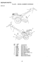
NO. 1 157384 2 157387 3 167386 4 110678X 5 110614X 6 102180X 7 156199 8 165266 9 120076X 11 165278 12 162384 -- 168499 -- 168500 DESCRIPTION Decal, Logo Decal, Description Decal, Logo Decal, Instruction, Tilling Decal, Hand Placement Decal, Shift Indicator Decal, Pnl Cntrl Reverse Decal, Briggs & Stratton Decal, Warning, Rotating Tines Decal, 5 HP Decal, Warning Till . Manual, Owner's (English) Manual, Owner's (French) REPAIR PARTS TILLER - - MODEL NUMBER CHDR500D DECALS 0 0 3 a 7 2 0 0 0 0 5 12 9 6 0 O 0 0 O 8 O KEY PART NO.
NO. 1 157384 2 157387 3 167386 4 110678X 5 110614X 6 102180X 7 156199 8 165266 9 120076X 11 165278 12 162384 -- 168499 -- 168500 DESCRIPTION Decal, Logo Decal, Description Decal, Logo Decal, Instruction, Tilling Decal, Hand Placement Decal, Shift Indicator Decal, Pnl Cntrl Reverse Decal, Briggs & Stratton Decal, Warning, Rotating Tines Decal, 5 HP Decal, Warning Till . Manual, Owner's (English) Manual, Owner's (French) REPAIR PARTS TILLER - - MODEL NUMBER CHDR500D DECALS 0 0 3 a 7 2 0 0 0 0 5 12 9 6 0 O 0 0 O 8 O KEY PART NO.


