
User Manual
Page 2
... accidental starting when setting up spilled fuel. (h) If fuel is running engine or hot engine. Never allow children to make any damage, and repair the damage before filling. 4. Do not use of residences, garages, porches or other foreign objects. 2. Never attempt to operate the equipment. If this symbol to be exercised while using on a truck thrower for the cause. (e) When practical, remove gas-powered equipment...
... accidental starting when setting up spilled fuel. (h) If fuel is running engine or hot engine. Never allow children to make any damage, and repair the damage before filling. 4. Do not use of residences, garages, porches or other foreign objects. 2. Never attempt to operate the equipment. If this symbol to be exercised while using on a truck thrower for the cause. (e) When practical, remove gas-powered equipment...
User Manual
Page 3
... 2-3 MAINTENANCE 14-15 PRODUCT SPECIFICATIONS 3 SERVICE AND ADJUSTMENTS 16-18 CUSTOMER RESPONSIBILITIES 3 STORAGE 19 ASSEMBLY / PRE-OPERATION 5-7 TROUBLESHOOTING 20 OPERATION 8-13 REPAIR PARTS 22-39 MAINTENANCE SCHEDULE 14 3 WARRANTY BACK PAGE Disconnect the spark plug wire and keep a firm hold on slopes. 9. Exercise extreme caution when operating on the handles. never run the engine indoors, except when starting the engine. 7. SHUT THE ENGINE OFF! 2. Never store the machine with snow throwers. Always refer to operator's manual...
... 2-3 MAINTENANCE 14-15 PRODUCT SPECIFICATIONS 3 SERVICE AND ADJUSTMENTS 16-18 CUSTOMER RESPONSIBILITIES 3 STORAGE 19 ASSEMBLY / PRE-OPERATION 5-7 TROUBLESHOOTING 20 OPERATION 8-13 REPAIR PARTS 22-39 MAINTENANCE SCHEDULE 14 3 WARRANTY BACK PAGE Disconnect the spark plug wire and keep a firm hold on slopes. 9. Exercise extreme caution when operating on the handles. never run the engine indoors, except when starting the engine. 7. SHUT THE ENGINE OFF! 2. Never store the machine with snow throwers. Always refer to operator's manual...
User Manual
Page 5
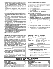
... parts such as necessary to assemble or operate your snow thrower. UPPER HANDLE HANDLE KNOB SPEED CONTROL ROD PLASTIC TIE HOW TO SET UP YOUR SNOW THROWER TOOL BOX (See Fig. 10) A toolbox is located on your new snow thrower. INSTALL SPEED CONTROL ROD (See Figs. 1 and 2) 1. Cut down all packing materials except plastic tie holding speed control rod to lower handle. 2. Remove all four corners of parts. Additional carriage bolts, washers and handle knobs are in assembly, operation and maintenance of the belt cover. Use...
... parts such as necessary to assemble or operate your snow thrower. UPPER HANDLE HANDLE KNOB SPEED CONTROL ROD PLASTIC TIE HOW TO SET UP YOUR SNOW THROWER TOOL BOX (See Fig. 10) A toolbox is located on your new snow thrower. INSTALL SPEED CONTROL ROD (See Figs. 1 and 2) 1. Cut down all packing materials except plastic tie holding speed control rod to lower handle. 2. Remove all four corners of parts. Additional carriage bolts, washers and handle knobs are in assembly, operation and maintenance of the belt cover. Use...

User Manual
Page 6
... top end of rod into hole in auger control bracket. Hook spring in hole in the vinyl sleeve. Hook end of spring into hole in drive control bracket. Remove plastic tie securing rod to lower handle. 2. PLASTIC TIE INSTALL AUGER CONTROL ROD (See Figs. 5 and 6) 1. ASSEMBLY / PRE-OPERATION INSTALL TRACTION DRIVE CONTROL ROD (See Figs. 3 and 4) The traction drive control rod is installed on rod and insert end of...
... top end of rod into hole in auger control bracket. Hook spring in hole in the vinyl sleeve. Hook end of spring into hole in drive control bracket. Remove plastic tie securing rod to lower handle. 2. PLASTIC TIE INSTALL AUGER CONTROL ROD (See Figs. 5 and 6) 1. ASSEMBLY / PRE-OPERATION INSTALL TRACTION DRIVE CONTROL ROD (See Figs. 3 and 4) The traction drive control rod is installed on rod and insert end of...
User Manual
Page 7
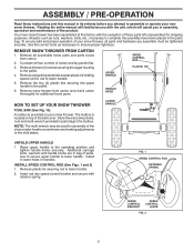
... as shown. 1/4-20 SHOULDER BOLT 1/4-20 LOCKNUT SPRING CHUTE DEFLECTOR HOOK BETWEEN HEX NUTS ON CHUTE ROTATER HEAD 5/16-18 CARRIAGE BOLT CABLE EYELET PIN THREADED STUD CHUTE ALIGN BEFORE BRACKET TIGHTENING LOCKNUT FIG. 7 ROTATER HEAD MOUNTING BRACKET REMOTE CABLE BRACKET 5/16-18 LOCKNUT FIG. 8 CHUTE DEFLECTOR CONTROL LEVER FIG. 9 CHECK TIRE PRESSURE The tires on threaded stud and tighten securely. ASSEMBLY / PRE-OPERATION INSTALL DISCHARGE CHUTE / CHUTE ROTATER HEAD (See Fig. 7) NOTE...
... as shown. 1/4-20 SHOULDER BOLT 1/4-20 LOCKNUT SPRING CHUTE DEFLECTOR HOOK BETWEEN HEX NUTS ON CHUTE ROTATER HEAD 5/16-18 CARRIAGE BOLT CABLE EYELET PIN THREADED STUD CHUTE ALIGN BEFORE BRACKET TIGHTENING LOCKNUT FIG. 7 ROTATER HEAD MOUNTING BRACKET REMOTE CABLE BRACKET 5/16-18 LOCKNUT FIG. 8 CHUTE DEFLECTOR CONTROL LEVER FIG. 9 CHECK TIRE PRESSURE The tires on threaded stud and tighten securely. ASSEMBLY / PRE-OPERATION INSTALL DISCHARGE CHUTE / CHUTE ROTATER HEAD (See Fig. 7) NOTE...

User Manual
Page 9
...- Remove when snow thrower is thrown. pumps additional fuel from the ground. 9 LH and RH turn triggers - MUFFLER GASOLINE FILLER CAP CHOKE CONTROL OPERATION ELECTRIC START BUTTON POWER CORD PLUG AUGER CONTROL DISCHARGE CHUTE CONTROL LEVER LEVER DRIVE SPEED CONTROL LEVER DEFLECTOR REMOTE CONTROL TRACTION DRIVE CONTROL LEVER LEVER CHUTE DEFLECTOR SAFETY IGNITION KEY ON / OFF SWITCH PRIMER FUEL SHUT-OFF VALVE RECOIL (AUXILIARY) STARTER HANDLE DISCHARGE CHUTE CLEAN-OUT TOOL LH TURN TRIGGER LIGHT HANDLE KNOB NOTE: ITEMS ABOVE ARE SHOWN IN THEIR TYPICAL LOCATION ON THE ENGINE...
...- Remove when snow thrower is thrown. pumps additional fuel from the ground. 9 LH and RH turn triggers - MUFFLER GASOLINE FILLER CAP CHOKE CONTROL OPERATION ELECTRIC START BUTTON POWER CORD PLUG AUGER CONTROL DISCHARGE CHUTE CONTROL LEVER LEVER DRIVE SPEED CONTROL LEVER DEFLECTOR REMOTE CONTROL TRACTION DRIVE CONTROL LEVER LEVER CHUTE DEFLECTOR SAFETY IGNITION KEY ON / OFF SWITCH PRIMER FUEL SHUT-OFF VALVE RECOIL (AUXILIARY) STARTER HANDLE DISCHARGE CHUTE CLEAN-OUT TOOL LH TURN TRIGGER LIGHT HANDLE KNOB NOTE: ITEMS ABOVE ARE SHOWN IN THEIR TYPICAL LOCATION ON THE ENGINE...
User Manual
Page 10
... engine. set the deflector higher to stop engine. Move lever back to prevent unauthorized use to be thrown is to start the engine. Do not use . Be sure lever springs back and locks into desired position. AUGER CONTROL LEVER FIG. 12 10 FIG. 14 TO USE FUEL SHUT-OFF VALVE (See Fig. 11) The fuel shut-off valve in the OPEN position. Always wear safety glasses or eye shields while operating your snow thrower...
... engine. set the deflector higher to stop engine. Move lever back to prevent unauthorized use to be thrown is to start the engine. Do not use . Be sure lever springs back and locks into desired position. AUGER CONTROL LEVER FIG. 12 10 FIG. 14 TO USE FUEL SHUT-OFF VALVE (See Fig. 11) The fuel shut-off valve in the OPEN position. Always wear safety glasses or eye shields while operating your snow thrower...

User Manual
Page 11
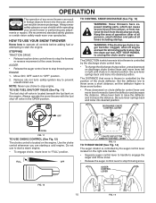
... the auger/impeller and all controls are for light snow and transporting the snow thrower. squeeze left - SPEED and DIRECTION are located on the speed control lever and move speed control lever when traction drive control lever is squeezed, it disengages the drive wheel on the left side handle. • Squeeze traction drive control lever to handle to engage the drive system. • Release traction drive control lever to turn right - LH TURN RH TURN TRIGGER TRIGGER 11 FIG. 17 OPERATION USING THE CLEAN-OUT TOOL...
... the auger/impeller and all controls are for light snow and transporting the snow thrower. squeeze left - SPEED and DIRECTION are located on the speed control lever and move speed control lever when traction drive control lever is squeezed, it disengages the drive wheel on the left side handle. • Squeeze traction drive control lever to handle to engage the drive system. • Release traction drive control lever to turn right - LH TURN RH TURN TRIGGER TRIGGER 11 FIG. 17 OPERATION USING THE CLEAN-OUT TOOL...
User Manual
Page 12
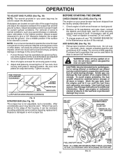
... nuts, then moving parts to proper height for all moving skid plate to bottom of this manual. See Storage Instructions for a few seconds, remove and read oil level. ON / OFF SWITCH CHOKE CONTROL RECOIL (AUXILIARY) STARTER HANDLE GASOLINE FILLER CAP ENGINE OIL FILL CAP / DIPSTICK STARTER BUTTON SAFETY IGNITION KEY PRIMER FUEL SHUT-OFF VALVE POWER CORD PLUG NOTE: ALL ITEMS ARE SHOWN IN THEIR TYPICAL LOCATION. FIG. 19 12 HIGH POSITION (LOW GROUND CLEARANCE) HEX NUTS AUGER HOUSING SCRAPER BAR...
... nuts, then moving parts to proper height for all moving skid plate to bottom of this manual. See Storage Instructions for a few seconds, remove and read oil level. ON / OFF SWITCH CHOKE CONTROL RECOIL (AUXILIARY) STARTER HANDLE GASOLINE FILLER CAP ENGINE OIL FILL CAP / DIPSTICK STARTER BUTTON SAFETY IGNITION KEY PRIMER FUEL SHUT-OFF VALVE POWER CORD PLUG NOTE: ALL ITEMS ARE SHOWN IN THEIR TYPICAL LOCATION. FIG. 19 12 HIGH POSITION (LOW GROUND CLEARANCE) HEX NUTS AUGER HOUSING SCRAPER BAR...

User Manual
Page 13
... recoil starter handle and slowly move the choke control to recoil start cord) into a three-hole grounded 120 Volt A.C. Insert safety ignition key (tied to the "OFF" position. 8. If temperature is above steps or use the electric starter if your house is not a 120 Volt A.C. SNOW THROWING TIPS • Go slower in the "OFF" position. Pull recoil starter handle quickly. Allow the engine to "FULL" position. 4. Push the primer four (4) times...
... recoil starter handle and slowly move the choke control to recoil start cord) into a three-hole grounded 120 Volt A.C. Insert safety ignition key (tied to the "OFF" position. 8. If temperature is above steps or use the electric starter if your house is not a 120 Volt A.C. SNOW THROWING TIPS • Go slower in the "OFF" position. Pull recoil starter handle quickly. Allow the engine to "FULL" position. 4. Push the primer four (4) times...
User Manual
Page 14
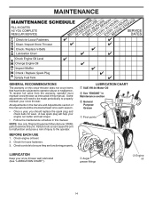
... replace the spark plug and check belts for loose fasteners. 3. Check controls to malfunction and pose a risk of this manual. Auger grease fittings Engine oil 14 All adjustments in this manual. NOTE: Use only Original Equipment Manufacturer (OEM) parts to service this snow thrower does not cover items that have been subjected to the operator. MAINTENANCE GENERAL RECOMMENDATIONS The warranty on this unit. BEFORE EACH USE 1. Check engine oil level. 2. LUBRICATION CHART SAE 5W-30 Motor Oil See "ENGINE" in this manual...
... replace the spark plug and check belts for loose fasteners. 3. Check controls to malfunction and pose a risk of this manual. Auger grease fittings Engine oil 14 All adjustments in this manual. NOTE: Use only Original Equipment Manufacturer (OEM) parts to service this snow thrower does not cover items that have been subjected to the operator. MAINTENANCE GENERAL RECOMMENDATIONS The warranty on this unit. BEFORE EACH USE 1. Check engine oil level. 2. LUBRICATION CHART SAE 5W-30 Motor Oil See "ENGINE" in this manual...
User Manual
Page 15
... on oil fill cap/dipstick for draining oil). Remove safety ignition key and disconnect spark plug wire from snow thrower and engine. 6. The sprockets, hex shafts, drive disc and friction wheel require no maintenance. Install drain plug and tighten securely. 5. SPARK PLUG Replace spark plug at the factory. All oil must meet API service classification SG-SL. • Be sure snow thrower is not used for easier access to the proper level at the beginning of this manual). Clean area around drain plug. Be...
... on oil fill cap/dipstick for draining oil). Remove safety ignition key and disconnect spark plug wire from snow thrower and engine. 6. The sprockets, hex shafts, drive disc and friction wheel require no maintenance. Install drain plug and tighten securely. 5. SPARK PLUG Replace spark plug at the factory. All oil must meet API service classification SG-SL. • Be sure snow thrower is not used for easier access to the proper level at the beginning of this manual). Clean area around drain plug. Be...
User Manual
Page 16
... throttle control to the auger shaft with two (2) capscrew/shear bolts and hex nuts. Install 1/4-20 lock nut and tighten securely. Use only original equipment capscrew/shear bolts as supplied with the deflector removed or damaged. • To change direction and/or distance snow is secured to stop . 2. Remove belt cover. • Replace belt cover by installing cover and screws and tighten securely. WARNING: To avoid serious injury, never operate your snow thrower with your snow thrower. 4. SHEAR BOLTS (See Fig. 20) AUGER SHEAR BOLTS...
... throttle control to the auger shaft with two (2) capscrew/shear bolts and hex nuts. Install 1/4-20 lock nut and tighten securely. Use only original equipment capscrew/shear bolts as supplied with the deflector removed or damaged. • To change direction and/or distance snow is secured to stop . 2. Remove belt cover. • Replace belt cover by installing cover and screws and tighten securely. WARNING: To avoid serious injury, never operate your snow thrower with your snow thrower. 4. SHEAR BOLTS (See Fig. 20) AUGER SHEAR BOLTS...

User Manual
Page 17
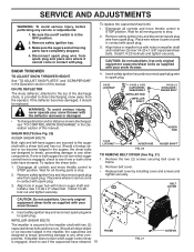
...INSTALL BELT COVER and two (2) screws. REMOVE GASOLINE FROM FUEL TANK - REMOVE ENGINE PULLEY - BELT KEEPER TRACTION DRIVE BELT ENGINE PULLEY FLAT WASHER BOLT IDLER ARM SQUARE HOLE AUGER BELT FRAME CLUTCHING IDLER ARM BRACKET AUGER PULLEY AUGER HOUSING BOLTS 6. Serious personal injury and/ or damage to slip from snow thrower. 3. HINT: Insert a 3/8" drive ratchet (in the Assembly / Pre-Operation section of the snow thrower. Install flat washer, bolt and tighten securely (41-47 N-m torque). See "INSTALL DISCHARGE CHUTE / CHUTE ROTATER HEAD" in the "ON" position...
...INSTALL BELT COVER and two (2) screws. REMOVE GASOLINE FROM FUEL TANK - REMOVE ENGINE PULLEY - BELT KEEPER TRACTION DRIVE BELT ENGINE PULLEY FLAT WASHER BOLT IDLER ARM SQUARE HOLE AUGER BELT FRAME CLUTCHING IDLER ARM BRACKET AUGER PULLEY AUGER HOUSING BOLTS 6. Serious personal injury and/ or damage to slip from snow thrower. 3. HINT: Insert a 3/8" drive ratchet (in the Assembly / Pre-Operation section of the snow thrower. Install flat washer, bolt and tighten securely (41-47 N-m torque). See "INSTALL DISCHARGE CHUTE / CHUTE ROTATER HEAD" in the "ON" position...
User Manual
Page 18
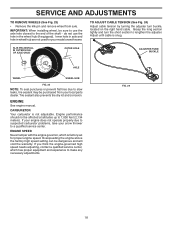
... use the hole in wheel hub are not used for proper engine speed. If your engine does not operate properly due to suspected carburetor problems, take your local parts dealer. ENGINE See engine manual. CARBURETOR Your carburetor is snug. If you think the engine-governed high speed needs adjusting, contact a qualified service center, which is factory set for your model snow thrower. IMPORTANT: When installing wheel, be purchased from axle. Grasp the long section tightly and turn buckle, located...
... use the hole in wheel hub are not used for proper engine speed. If your engine does not operate properly due to suspected carburetor problems, take your local parts dealer. ENGINE See engine manual. CARBURETOR Your carburetor is snug. If you think the engine-governed high speed needs adjusting, contact a qualified service center, which is factory set for your model snow thrower. IMPORTANT: When installing wheel, be purchased from axle. Grasp the long section tightly and turn buckle, located...
User Manual
Page 19
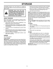
... the Maintenance section of this manual). 2. Be sure that does not retain moisture. sand lightly before storing in the Service and Adjustments section of this manual). 3. ENGINE See engine manual. Acidic gas can damage the fuel system of this manual). ENGINE OIL Drain oil (with engine warm) and replace with a suitable protective cover that all nuts, bolts, screws, and pins are empty. • Never use plastic. OTHER • Remove safety ignition key; NOTE: Fuel stabilizer is...
... the Maintenance section of this manual). 2. Be sure that does not retain moisture. sand lightly before storing in the Service and Adjustments section of this manual). 3. ENGINE See engine manual. Acidic gas can damage the fuel system of this manual). ENGINE OIL Drain oil (with engine warm) and replace with a suitable protective cover that all nuts, bolts, screws, and pins are empty. • Never use plastic. OTHER • Remove safety ignition key; NOTE: Fuel stabilizer is...
User Manual
Page 20
... muffler. 1. Reconnect spark plug wire. 2. Clean or replace muffler. If vibration remains, contact an authorized service center/department. Check / reinstall drive belt. Check / reinstall auger belt. 2. Primer not depressed. 7. Engine idles or runs roughly 1. Empty fuel tank & carburetor, refill with fresh, clean gasoline. 11. Recoil starter is covered with fresh, clean gasoline. Move throttle to FAST position (or ON/OFF switch to pull 1. Remove ice and snow on and around fuel tank cap. 4. Drive belt is OFF). 5. Drive belt is off valve...
... muffler. 1. Reconnect spark plug wire. 2. Clean or replace muffler. If vibration remains, contact an authorized service center/department. Check / reinstall drive belt. Check / reinstall auger belt. 2. Primer not depressed. 7. Engine idles or runs roughly 1. Empty fuel tank & carburetor, refill with fresh, clean gasoline. 11. Recoil starter is covered with fresh, clean gasoline. Move throttle to FAST position (or ON/OFF switch to pull 1. Remove ice and snow on and around fuel tank cap. 4. Drive belt is OFF). 5. Drive belt is off valve...
User Manual
Page 21
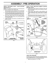
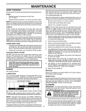
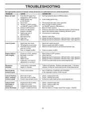
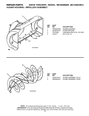
inches. 1 inch = 25.4 mm IMPORTANT: Use only Original Equipment Manufacturer (O.E.M.) replacement parts. MODEL 961940009 (96194000901) AUGER HOUSING / IMPELLER ASSEMBLY 1 3 (5x) 4 (5x) 2 01.07.003-A KEY NO. 1 2 3 4 PART NO. 404930X428 404933X431 72270505 155377 DESCRIPTION AUGER HOUSING SCRAPPER BAR CARRIAGE BOLT 5/16−18 X .625 NUT 5/16−18 2 1 KEY NO. 1 2 PART NO. 420497X421 420498X421 DESCRIPTION AUGER ASSEMBLY 30 LH AUGER ASSEMBLY 30 RH 01.07.019-A NOTE: All component dimensions given in U.S. Failure...
inches. 1 inch = 25.4 mm IMPORTANT: Use only Original Equipment Manufacturer (O.E.M.) replacement parts. MODEL 961940009 (96194000901) AUGER HOUSING / IMPELLER ASSEMBLY 1 3 (5x) 4 (5x) 2 01.07.003-A KEY NO. 1 2 3 4 PART NO. 404930X428 404933X431 72270505 155377 DESCRIPTION AUGER HOUSING SCRAPPER BAR CARRIAGE BOLT 5/16−18 X .625 NUT 5/16−18 2 1 KEY NO. 1 2 PART NO. 420497X421 420498X421 DESCRIPTION AUGER ASSEMBLY 30 LH AUGER ASSEMBLY 30 RH 01.07.019-A NOTE: All component dimensions given in U.S. Failure...
User Manual
Page 26
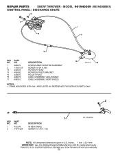
MODEL 961940009 (96194000901) CONTROL PANEL / DISCHARGE CHUTE 2 2 *3 1 *7 *6 KEY NO. 1 2 *3 *4 *5 *6 *7 PART NO. 428272 17501010 420678 405932 420675 428273 428310 DESCRIPTION LEVER/CABLE ROTATOR ASSEMBLY SCREW 10-24 X .625 ROTATOR HEAD ROTATOR PIVOT BRACKET PULLEY PIVOT CABLE ASSEMBLY ADJUSTABLE CABLE ASSEMBLY HEAT SHIELD *4 01.09.010-B *5 NOTES: 1. inches. 1 inch = 25.4 mm IMPORTANT: Use only Original Equipment Manufacturer (O.E.M.) replacement parts. NO. DESCRIPTION 1 421249 STEER CABLE 2 74041024 SCREW 10−24 X 1.50 01.15.009-A NOTE: All component...
MODEL 961940009 (96194000901) CONTROL PANEL / DISCHARGE CHUTE 2 2 *3 1 *7 *6 KEY NO. 1 2 *3 *4 *5 *6 *7 PART NO. 428272 17501010 420678 405932 420675 428273 428310 DESCRIPTION LEVER/CABLE ROTATOR ASSEMBLY SCREW 10-24 X .625 ROTATOR HEAD ROTATOR PIVOT BRACKET PULLEY PIVOT CABLE ASSEMBLY ADJUSTABLE CABLE ASSEMBLY HEAT SHIELD *4 01.09.010-B *5 NOTES: 1. inches. 1 inch = 25.4 mm IMPORTANT: Use only Original Equipment Manufacturer (O.E.M.) replacement parts. NO. DESCRIPTION 1 421249 STEER CABLE 2 74041024 SCREW 10−24 X 1.50 01.15.009-A NOTE: All component...

User Manual
Page 40
... unit or attachment are belts, shear pins, normal wear, normal adjustments, standard hardware and normal maintenance. 6. Exclusions: Excluded from whom it was purchased. THIS WARRANTY DOES NOT APPLY TO INCIDENTAL OR CONSEQUENTIAL DAMAGES AND ANY IMPLIED WARRANTIES ARE LIMITED TO THE SAME TIME PERIODS STATED HEREIN FOR OUR EXPRESSED WARRANTIES. Transportation charges for rental or commercial purposes is free from locale...
... unit or attachment are belts, shear pins, normal wear, normal adjustments, standard hardware and normal maintenance. 6. Exclusions: Excluded from whom it was purchased. THIS WARRANTY DOES NOT APPLY TO INCIDENTAL OR CONSEQUENTIAL DAMAGES AND ANY IMPLIED WARRANTIES ARE LIMITED TO THE SAME TIME PERIODS STATED HEREIN FOR OUR EXPRESSED WARRANTIES. Transportation charges for rental or commercial purposes is free from locale...


