
User Manual
Page 2
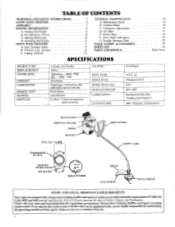
...U.S. Check with adjustable fuel mixture jets Push Button Auto Rewind Lo Tone - Fueling Your Engine B. Drive Shaft Lubrication 11 G. Failure to Temperature Limiting Muffler and Spark Arresting requirements. Trimmer Line Advance C. Maintenance Safety 7 B. Champion CI-14 .025 " .010'7.014" Gasoline/Oil Mix (See "Fueling Your Engine") .080 " Diameter, monofilament REAR HANDLE THROTTLE TRIGGER CHOKE BRACKET FUEL CAP --v.- Line Trimmer Safety B. Pre-Operation Checks C. Forest Land and the states of these parts. Starting Instructions D. Air Filter 10 E. Starter Rope 10...
...U.S. Check with adjustable fuel mixture jets Push Button Auto Rewind Lo Tone - Fueling Your Engine B. Drive Shaft Lubrication 11 G. Failure to Temperature Limiting Muffler and Spark Arresting requirements. Trimmer Line Advance C. Maintenance Safety 7 B. Champion CI-14 .025 " .010'7.014" Gasoline/Oil Mix (See "Fueling Your Engine") .080 " Diameter, monofilament REAR HANDLE THROTTLE TRIGGER CHOKE BRACKET FUEL CAP --v.- Line Trimmer Safety B. Pre-Operation Checks C. Forest Land and the states of these parts. Starting Instructions D. Air Filter 10 E. Starter Rope 10...
User Manual
Page 5
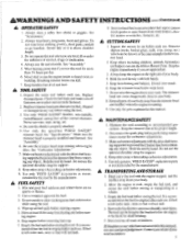
... the engine is recommended that the fuel be hung by the bracket below waist level. 7. A TOOL SAFETY 1. Replace damaged parts. Replace trimmer head parts that are approached. 3. Make sure the trimmer head is properly attached. 5. Do not use . Store tool and fuel in a vehicle. 3. Remove objects (rocks, broken glass, nails, wire, string, etc.) which can be emptied after each use the optional shoulder strap for support. 4. Use only for this tool for carburetor adjustments. 3. If fuel...
... the engine is recommended that the fuel be hung by the bracket below waist level. 7. A TOOL SAFETY 1. Replace damaged parts. Replace trimmer head parts that are approached. 3. Make sure the trimmer head is properly attached. 5. Do not use . Store tool and fuel in a vehicle. 3. Remove objects (rocks, broken glass, nails, wire, string, etc.) which can be emptied after each use the optional shoulder strap for support. 4. Use only for this tool for carburetor adjustments. 3. If fuel...
User Manual
Page 6
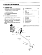
... so. 2. Do not use genuine Weed Eater® parts. 5 9 13 11 10 SAFETY LABEL e grease t.; Engine 1 Drive Shaft/Bearing Assembly w/Safety Label 1 Shield 1 Trimmer Head 1 Assist Handle 1 Operator's Manual (not shown) 1 Loose Parts Bag (not shown) 1 * LOOSE PARTS BAG CONTENTS: 6 Flex Shaft Lube 1 7 Screw, Shield 2 8 Bracket-Shield 1 9 Hex Bolt, Assist Handle 1 10 Washer, Flat, Assist Handle 1 11 Wing Nut, Assist Handle 1 12 Clamp-Engine Shroud 1 13 Bolt-Engine Shroud 1 14 Nut-Engine Shroud 1 * Weed Eater® hardware parts are Grade 5 or...
... so. 2. Do not use genuine Weed Eater® parts. 5 9 13 11 10 SAFETY LABEL e grease t.; Engine 1 Drive Shaft/Bearing Assembly w/Safety Label 1 Shield 1 Trimmer Head 1 Assist Handle 1 Operator's Manual (not shown) 1 Loose Parts Bag (not shown) 1 * LOOSE PARTS BAG CONTENTS: 6 Flex Shaft Lube 1 7 Screw, Shield 2 8 Bracket-Shield 1 9 Hex Bolt, Assist Handle 1 10 Washer, Flat, Assist Handle 1 11 Wing Nut, Assist Handle 1 12 Clamp-Engine Shroud 1 13 Bolt-Engine Shroud 1 14 Nut-Engine Shroud 1 * Weed Eater® hardware parts are Grade 5 or...
User Manual
Page 7
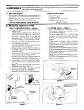
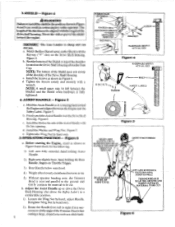
... the Engine Shroud Opening. Wrenches: 1-1/4 inch or Adjustable Wrench 2.TRIMMER HEAD - Figure 2 a. Remove the packing cover from theend ofthe Drive Shaft Housing. c. NOTE: To remove Trimmer Head, hold the Dust Cup with a wrench and unthread the Trimmer Head counterclockwise I-1/4 " WRENCH DIRECTION TO INSTALL 0 NUT • ti ro FLEXIBLE DRIVE SHAFT MARK 1'h " SCREW KEYWAY KEY DRIVE SHAFT HOUSING Figure 2 ARBOR SHAFT DUST CUP Approximately 2 inches of 4 inches. TAP BUTTON HARDWARE SHOWN ACTUAL SIZE Figure 1 Figure 3 7 PREPARATION This Operator's Manual has...
... the Engine Shroud Opening. Wrenches: 1-1/4 inch or Adjustable Wrench 2.TRIMMER HEAD - Figure 2 a. Remove the packing cover from theend ofthe Drive Shaft Housing. c. NOTE: To remove Trimmer Head, hold the Dust Cup with a wrench and unthread the Trimmer Head counterclockwise I-1/4 " WRENCH DIRECTION TO INSTALL 0 NUT • ti ro FLEXIBLE DRIVE SHAFT MARK 1'h " SCREW KEYWAY KEY DRIVE SHAFT HOUSING Figure 2 ARBOR SHAFT DUST CUP Approximately 2 inches of 4 inches. TAP BUTTON HARDWARE SHOWN ACTUAL SIZE Figure 1 Figure 3 7 PREPARATION This Operator's Manual has...
User Manual
Page 8
... the Drive Shaft Housing above the Safety Label ) to a comfortable position. 1). Hold the Assist Handle so it is sharp and can cut . Rear Handle below waist level. 4). Retighten Wing Nut by hand, adjust Handle. d. Install the Washer and Wing Nut. a. Figure 4. c. Install the Bolt in Figure 4. Install the Screws as shown in Figure 6 and check for the following: 1). Figure 5. Tighten the Wing Nut by hand only S.OPERATING POSITION Figure 6 a Before starting the Engine...
... the Drive Shaft Housing above the Safety Label ) to a comfortable position. 1). Hold the Assist Handle so it is sharp and can cut . Rear Handle below waist level. 4). Retighten Wing Nut by hand, adjust Handle. d. Install the Washer and Wing Nut. a. Figure 4. c. Install the Bolt in Figure 4. Install the Screws as shown in Figure 6 and check for the following: 1). Figure 5. Tighten the Wing Nut by hand only S.OPERATING POSITION Figure 6 a Before starting the Engine...
User Manual
Page 9
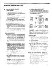
... POULAN®/WEED EATER° 2-cycle EngineOil isstrongly recommended for one blended to be mixed at a 16:1 ratio (16 parts gasoline to 1 part oil) and the other at operating temperatures common to 2-cycle engines, resulting in tank, store so fuel will foul the spark plug. Does not have proven that the fuel tank be clean and not over two months old. g. See "Specifications," for fuel. Use a container approved for location. Empty the fuel tank before removing fuel cap. h. ENGINE...
... POULAN®/WEED EATER° 2-cycle EngineOil isstrongly recommended for one blended to be mixed at a 16:1 ratio (16 parts gasoline to 1 part oil) and the other at operating temperatures common to 2-cycle engines, resulting in tank, store so fuel will foul the spark plug. Does not have proven that the fuel tank be clean and not over two months old. g. See "Specifications," for fuel. Use a container approved for location. Empty the fuel tank before removing fuel cap. h. ENGINE...
User Manual
Page 10
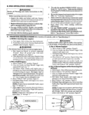
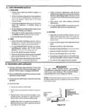
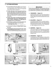
... using this tool by the manufacturer. 10. Keep others away when making carburetor adjustments. 9. Use only WEED EATER® accessories as engine starts. Fuel engine. Extend line 4 inches from Trimmer Head to "off ' position. c. Pull Starter Rope sharply until engine runs, but no more pulls. NOTE:Ifengine has not startedafter5 pulls, repeat steps "a" through step "f." Figure 8. c. Figure 8. 4. Move Choke to "Specifications.") 1. Grip rear handle and keep Throttle Trigger fully squeezed until engine runs. f. NOTE: If engine dies with the shield properly attached...
... using this tool by the manufacturer. 10. Keep others away when making carburetor adjustments. 9. Use only WEED EATER® accessories as engine starts. Fuel engine. Extend line 4 inches from Trimmer Head to "off ' position. c. Pull Starter Rope sharply until engine runs, but no more pulls. NOTE:Ifengine has not startedafter5 pulls, repeat steps "a" through step "f." Figure 8. c. Figure 8. 4. Move Choke to "Specifications.") 1. Grip rear handle and keep Throttle Trigger fully squeezed until engine runs. f. NOTE: If engine dies with the shield properly attached...
User Manual
Page 11
... cutting. DAMAGED TRIMMER HEAD Trimmer head parts that are approached. -40 Tap-N-Go® Trimmer Head #701574 Use Only Genuine Weed Eater® Parts AWARNING --- a. For correction, refer to "Assembly-Drive Shaft Housing!' b. Hold button down until the engine stops. Serial No. 2. At lower speeds, there is properly seated in any way, can fly apart and cause serious injury. Keep others at a higher speed than full throttle. b. Replace damaged parts before using the tool. 11 OPERATING INSTRUCTIONS...
... cutting. DAMAGED TRIMMER HEAD Trimmer head parts that are approached. -40 Tap-N-Go® Trimmer Head #701574 Use Only Genuine Weed Eater® Parts AWARNING --- a. For correction, refer to "Assembly-Drive Shaft Housing!' b. Hold button down until the engine stops. Serial No. 2. At lower speeds, there is properly seated in any way, can fly apart and cause serious injury. Keep others at a higher speed than full throttle. b. Replace damaged parts before using the tool. 11 OPERATING INSTRUCTIONS...
User Manual
Page 12
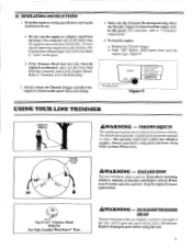
... the line is being operated. • To advance line: AWARNICKG Use only WEED EATER® flexible, non-metallic, monofilament cutting line. Replace damaged parts. Keep others away when making carburetor adjustments. Use only WEED EATER® accessories as rope, wire, string, etc. Inspect thearea tobecut beforeeach use . b. Always keep the shield in the trimmer head. Wire can be required to "Assembly" e. Secure hair so it is properly attached. e. Keep handles free of the correct diameter. Operate the engine...
... the line is being operated. • To advance line: AWARNICKG Use only WEED EATER® flexible, non-metallic, monofilament cutting line. Replace damaged parts. Keep others away when making carburetor adjustments. Use only WEED EATER® accessories as rope, wire, string, etc. Inspect thearea tobecut beforeeach use . b. Always keep the shield in the trimmer head. Wire can be required to "Assembly" e. Secure hair so it is properly attached. e. Keep handles free of the correct diameter. Operate the engine...
User Manual
Page 13
... or scalping, use less than full throttle to do the cutting. SWEEPING - Keep the line parallel to strike the ground around walls, fences, trees and flower beds, but it also can be used for mowing in Figure II. • The line will easily remove grass and weeds from around trees, posts, monuments, etc. You will cause trimmer head damage and premature...
... or scalping, use less than full throttle to do the cutting. SWEEPING - Keep the line parallel to strike the ground around walls, fences, trees and flower beds, but it also can be used for mowing in Figure II. • The line will easily remove grass and weeds from around trees, posts, monuments, etc. You will cause trimmer head damage and premature...
User Manual
Page 14
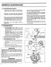
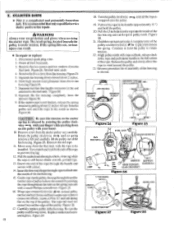
... RESS LOCK TAB TURN LOCK RING COUNTERCLOCKWISE Figure 16 SPOOL LINE SAVER LUG DRIVE GEAR LOCK RING ) SPOOL HOUSING LINE SAVER CATCH Figure 17 CATCH LOCK TAB set 40,PBB,401....----- Maintain the tool according to provide a new wear surface. Disconnect the spark plug before using the tool. 8. d. Inspect all parts. Replace damaged parts before performing maintenance except for carburetor adjustments. 3. Check for replacing line as well as optimum performance. Pre-wound spools offer the most convenient method for fuel...
... RESS LOCK TAB TURN LOCK RING COUNTERCLOCKWISE Figure 16 SPOOL LINE SAVER LUG DRIVE GEAR LOCK RING ) SPOOL HOUSING LINE SAVER CATCH Figure 17 CATCH LOCK TAB set 40,PBB,401....----- Maintain the tool according to provide a new wear surface. Disconnect the spark plug before using the tool. 8. d. Inspect all parts. Replace damaged parts before performing maintenance except for carburetor adjustments. 3. Check for replacing line as well as optimum performance. Pre-wound spools offer the most convenient method for fuel...
User Manual
Page 15
... change the spool from the trimmer head. To replace the line on existing spool: (.)Follow "Installing Spool w/Line," steps "a-d:' and remove any line remaining on it. Figure 22. Continuewith steps "e-i' TURN LOCK RISC CLOCKWISE TO INSTALL fin Figure 19 -s-r. Turn and lock spool under lugs on theline to 1/8 inch of the end of the line through the hole in size, orbroken off or backs up in housing. Check to the operating position. Place spool in the Trimmer Head...
... change the spool from the trimmer head. To replace the line on existing spool: (.)Follow "Installing Spool w/Line," steps "a-d:' and remove any line remaining on it. Figure 22. Continuewith steps "e-i' TURN LOCK RISC CLOCKWISE TO INSTALL fin Figure 19 -s-r. Turn and lock spool under lugs on theline to 1/8 inch of the end of the line through the hole in size, orbroken off or backs up in housing. Check to the operating position. Place spool in the Trimmer Head...
User Manual
Page 16
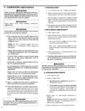
... "1. High Speed Mixture Adjustment." - Engine does not return to idle. Deceleration Check:' - Basic Carburetor Settings?' • This is important to the length allowed by cleaning the air filter. b. Allow engine to idle from full throttle within 2 seconds. c. Deceleration Check." 2.) If the engine does not accelerate smoothly, turn at idlespeed toavoidseriousinjury to "Specifications" for support. Repeat steps "b." Make sure the line extends to follow instructions in sequence as described in the adjusting screws. Adjust IdleSpeed Screw (Figure23...
... "1. High Speed Mixture Adjustment." - Engine does not return to idle. Deceleration Check:' - Basic Carburetor Settings?' • This is important to the length allowed by cleaning the air filter. b. Allow engine to idle from full throttle within 2 seconds. c. Deceleration Check." 2.) If the engine does not accelerate smoothly, turn at idlespeed toavoidseriousinjury to "Specifications" for support. Repeat steps "b." Make sure the line extends to follow instructions in sequence as described in the adjusting screws. Adjust IdleSpeed Screw (Figure23...
User Manual
Page 17
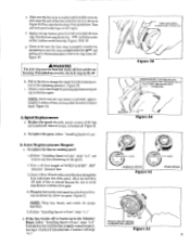
... location, see "Specifications:' 2. Support thedriveshaft housing sothe trimmer line is satisfactory; through "6. d. Turn High Speed Mixture Screw (Figure 23) very slowly clockwise -4 until engine speed is clean. Acceleration Check" and "4. CAUTION: If the engine does not operate accordingto theseinstructionsafter repeatingthe adjusting steps, do not use the tool. REINSTALL AIR FILTER Be sure filter is reduced. Deceleration Check?" Turn the Low Speed Mixture Screw and the High Speed Mixture Screw(Figure23)clockwise 4,-* just until the speed increases and then starts...
... location, see "Specifications:' 2. Support thedriveshaft housing sothe trimmer line is satisfactory; through "6. d. Turn High Speed Mixture Screw (Figure 23) very slowly clockwise -4 until engine speed is clean. Acceleration Check" and "4. CAUTION: If the engine does not operate accordingto theseinstructionsafter repeatingthe adjusting steps, do not use the tool. REINSTALL AIR FILTER Be sure filter is reduced. Deceleration Check?" Turn the Low Speed Mixture Screw and the High Speed Mixture Screw(Figure23)clockwise 4,-* just until the speed increases and then starts...
User Manual
Page 18
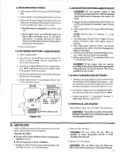
... and gloves when servicing thestarter rope. If the spring flies out, serious injury can result. • To repair or replace: 1_ Disconnect spark plug wire. 2. Figure 24. Figure26. 8. Insert the free end of rope through from tank. 3. Figure 28. 17. Carefully replace pulley in fan housing.Figure 26. 7. Pull out the rope by pulling about 2 inches. 6. AIR FILTER REMOVE THE FIVE SCREWS 0 REMOVE SCREW REMOVE SCREW tt Figure 24 FAN HOUSING-4w FUEL LINE * fir Figure 2.5 IGNITION MODULE vea "OFF...
... and gloves when servicing thestarter rope. If the spring flies out, serious injury can result. • To repair or replace: 1_ Disconnect spark plug wire. 2. Figure 24. Figure26. 8. Insert the free end of rope through from tank. 3. Figure 28. 17. Carefully replace pulley in fan housing.Figure 26. 7. Pull out the rope by pulling about 2 inches. 6. AIR FILTER REMOVE THE FIVE SCREWS 0 REMOVE SCREW REMOVE SCREW tt Figure 24 FAN HOUSING-4w FUEL LINE * fir Figure 2.5 IGNITION MODULE vea "OFF...
User Manual
Page 19
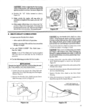
... surface of operation. - DRIVE SHAFT LUBRICATION • Lubricate the Flexible Drive Shaft: - Remove the Flexible Drive Shaft from the Drive Shaft Housing as shown. Using a clean cloth, wipe the surface of the Drive Shaft Housing. 7. CAUTION: Before replacing the fan housing, makecertainthat the"off " button. 26. I PULLEY ROPE NOTCH GROOVE Figure 29 ATUU PULLEY---NOTCH ROPE GROOVE Figure 30 F. l I PULLEY SCREW / PULLEY RATCHET PULLEY_ ,„„0 HOLES f. Part No. 30102. Figure 1. 2. Even after wiping theshaft, grease residuecan...
... surface of operation. - DRIVE SHAFT LUBRICATION • Lubricate the Flexible Drive Shaft: - Remove the Flexible Drive Shaft from the Drive Shaft Housing as shown. Using a clean cloth, wipe the surface of the Drive Shaft Housing. 7. CAUTION: Before replacing the fan housing, makecertainthat the"off " button. 26. I PULLEY ROPE NOTCH GROOVE Figure 29 ATUU PULLEY---NOTCH ROPE GROOVE Figure 30 F. l I PULLEY SCREW / PULLEY RATCHET PULLEY_ ,„„0 HOLES f. Part No. 30102. Figure 1. 2. Even after wiping theshaft, grease residuecan...
User Manual
Page 20
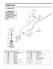
... QTY. REQ. 1 1 2 1 2 1 1 1 - DESCRIPTION Wing Nut-#1/4-20 Washer-#1/4 Flat Screw-Line Limiter (#10-24x1") Limiter-Line Nut-Line Limiter Screw Drive Shaft Ass'y (Incl. #12) Flexible Shaft Assembly Flex Shaft Lube-Optional 1 Decal-Shaft Warning 1 Operator's Manual 21 PARTS LIST A. LOWER UNIT /WARNING All repairs, adjustments and maintenance not described in the Operator's Manual must be performed by a qualified service dealer to avoid creating a hazard. 17 24 z3- 2 3 4 5 I 6 kti - 16 26 i grease E' 9 KEY NO. 1 2 3 4 5 6 7 8 9 10...
... QTY. REQ. 1 1 2 1 2 1 1 1 - DESCRIPTION Wing Nut-#1/4-20 Washer-#1/4 Flat Screw-Line Limiter (#10-24x1") Limiter-Line Nut-Line Limiter Screw Drive Shaft Ass'y (Incl. #12) Flexible Shaft Assembly Flex Shaft Lube-Optional 1 Decal-Shaft Warning 1 Operator's Manual 21 PARTS LIST A. LOWER UNIT /WARNING All repairs, adjustments and maintenance not described in the Operator's Manual must be performed by a qualified service dealer to avoid creating a hazard. 17 24 z3- 2 3 4 5 I 6 kti - 16 26 i grease E' 9 KEY NO. 1 2 3 4 5 6 7 8 9 10...

User Manual
Page 22
...1 Decal-Starting Instructions 1 Decal-Choke/OFF 1 Decal-Shroud (Right)-Not Shown 1 Decal-Shroud (Left)-Not Shown 23 DESCRIPTION 1 Fuel Cap Assembly (Incl. 0 -Ring) 1 Bracket-Fuel Tank 1 Screw-Bracket Handle (#1/4-10x1-1/8") 1 Fuel Tank Ass'y. (Incl. #1, 16 & 37) 2 Screw-Fuel Tank Fan Hsg. (#10x1") 2 Washer-Fuel Tank Fan Hsg. 4 Screw 1 Air Filter 1 Handle, Starter 1 Fan Housing Ass'y. 2 Screw-Fan Housing-Bottom #10-24x1-1/8 Bind. Hd. 1 Throttle Wire 1 Rope Kit 1 Screw 1 FuelPick-Up Ass'y. 1 Starter-Recoil Spring 1 Starter-Pulley 1 Button-Kill Switch...
...1 Decal-Starting Instructions 1 Decal-Choke/OFF 1 Decal-Shroud (Right)-Not Shown 1 Decal-Shroud (Left)-Not Shown 23 DESCRIPTION 1 Fuel Cap Assembly (Incl. 0 -Ring) 1 Bracket-Fuel Tank 1 Screw-Bracket Handle (#1/4-10x1-1/8") 1 Fuel Tank Ass'y. (Incl. #1, 16 & 37) 2 Screw-Fuel Tank Fan Hsg. (#10x1") 2 Washer-Fuel Tank Fan Hsg. 4 Screw 1 Air Filter 1 Handle, Starter 1 Fan Housing Ass'y. 2 Screw-Fan Housing-Bottom #10-24x1-1/8 Bind. Hd. 1 Throttle Wire 1 Rope Kit 1 Screw 1 FuelPick-Up Ass'y. 1 Starter-Recoil Spring 1 Starter-Pulley 1 Button-Kill Switch...
User Manual
Page 23
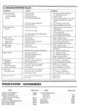
Idle speed set too high. 3. Air filter dirty. 2. Carburetor requires adjustment. 2. Carburetor requires adjustments. 3. Drive shaft broken or not engaged. 2. Line improperly wound onto spool. 2. Check for a few seconds after starting CAUSE 1. Adjust idle speed screw clockwise to reduce speed. 3. Clean or replace air filter. 2. See "Carburetor Adjustments." I . See "Carburet Adjustments." 2. I . ITEM 701601 701506 701534 701523 701574 701570 701548 2-CYCLE ENGINE OIL -8 OZ. (16:1) -8 OZ. (32:1) -4 OZ. (32:1) FUEL CAP AIR FILTER SPARK PLUG STOCK NO. 3039 30117 30119...
Idle speed set too high. 3. Air filter dirty. 2. Carburetor requires adjustment. 2. Carburetor requires adjustments. 3. Drive shaft broken or not engaged. 2. Line improperly wound onto spool. 2. Check for a few seconds after starting CAUSE 1. Adjust idle speed screw clockwise to reduce speed. 3. Clean or replace air filter. 2. See "Carburetor Adjustments." I . See "Carburet Adjustments." 2. I . ITEM 701601 701506 701534 701523 701574 701570 701548 2-CYCLE ENGINE OIL -8 OZ. (16:1) -8 OZ. (32:1) -4 OZ. (32:1) FUEL CAP AIR FILTER SPARK PLUG STOCK NO. 3039 30117 30119...
User Manual
Page 24
... changes and improvements are not available directly from those related to your tool when improvements are made available, especially those described in this Operator's Manual, please contact your unit. Always update your local dealer(s). Parts and repair service are sent to rigid quality standards. b. Description of your local Poulan/Weed Eater Dealer for trimmers, Brushcutters and Blowers) or Skil Service Center (under "tools-electric"). 2. FOR SERVICE OR REPLACEMENT PARTS...
... changes and improvements are not available directly from those related to your tool when improvements are made available, especially those described in this Operator's Manual, please contact your unit. Always update your local dealer(s). Parts and repair service are sent to rigid quality standards. b. Description of your local Poulan/Weed Eater Dealer for trimmers, Brushcutters and Blowers) or Skil Service Center (under "tools-electric"). 2. FOR SERVICE OR REPLACEMENT PARTS...


