
PA D5000.5 Owner's Manual
Page 2
...; PA D5000.5-100W X 4, 400W X 1, RMS @ 2 Ohms; 70W X 4, 200W X 1, RMS @ 4 Ohms 200W X 2, RMS bridged @ 4 Ohms; 500W X 1, RMS @ 1 Ohm (sub) Note: Improper installation will not only limit the performance of your original carton and packing materials in case you need to ship the unit in mind and always use . We recommend keeping your Polk Audio PA D Series...
...; PA D5000.5-100W X 4, 400W X 1, RMS @ 2 Ohms; 70W X 4, 200W X 1, RMS @ 4 Ohms 200W X 2, RMS bridged @ 4 Ohms; 500W X 1, RMS @ 1 Ohm (sub) Note: Improper installation will not only limit the performance of your original carton and packing materials in case you need to ship the unit in mind and always use . We recommend keeping your Polk Audio PA D Series...

PA D5000.5 Owner's Manual
Page 3
...the remote turn on lead of the head unit. 3. +12V Power-Connect this terminal through metal car walls • Amplifier Power Wire End Panel Layouts PA D5000.5 Line Level Inputs/Controls 2 3 45 6 7 8 3 45 6 7 8 INPUT SUB SUB INT SUB LEVEL SONIC REMOTE LEVEL CONTROL LPF SUB 1... input from your head unit. 4 LPF HPF 1 INXP-OUVTER OUTPUT X-OVER FREQ x 1 FREQ x 1 INPUT OUTPUT © 2011 Polk Audio-all rights reserved PA D2000.2 6. The FULL setting does not attenuate any frequencies and is used with mid-range speakers and tweeters. Set the switch to ST ...
...the remote turn on lead of the head unit. 3. +12V Power-Connect this terminal through metal car walls • Amplifier Power Wire End Panel Layouts PA D5000.5 Line Level Inputs/Controls 2 3 45 6 7 8 3 45 6 7 8 INPUT SUB SUB INT SUB LEVEL SONIC REMOTE LEVEL CONTROL LPF SUB 1... input from your head unit. 4 LPF HPF 1 INXP-OUVTER OUTPUT X-OVER FREQ x 1 FREQ x 1 INPUT OUTPUT © 2011 Polk Audio-all rights reserved PA D2000.2 6. The FULL setting does not attenuate any frequencies and is used with mid-range speakers and tweeters. Set the switch to ST ...

PA D5000.5 Owner's Manual
Page 4
... on the amplifier. • Add extra ground wire between the negative terminal of the battery and the chassis. 5000.5 Speaker Wiring Diagram PA D5000.5 SUB RL RR FL FR SUB RL RR FL FR GND REM 12V SUB RL RR FL FR 40A 40A SUB RL RR FL... down is generated. For optimal results, mount the amplifier with a short, heavy gauge wire connected directly to turn -on a stable, flat surface. Polk Audio PA D Series amplifiers do not restrict the airflow around the amplifier is also recommended. 10. The amplifier should take into a single full range channel with crimped...
... on the amplifier. • Add extra ground wire between the negative terminal of the battery and the chassis. 5000.5 Speaker Wiring Diagram PA D5000.5 SUB RL RR FL FR SUB RL RR FL FR GND REM 12V SUB RL RR FL FR 40A 40A SUB RL RR FL... down is generated. For optimal results, mount the amplifier with a short, heavy gauge wire connected directly to turn -on a stable, flat surface. Polk Audio PA D Series amplifiers do not restrict the airflow around the amplifier is also recommended. 10. The amplifier should take into a single full range channel with crimped...
PA D5000.5 Owner's Manual
Page 5
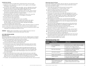
... connections to their minimum positions. 4. Set any tone controls to be on page 4). 1. Turn the level controls of your Polk Audio PA D Series amplifier. Audio input not connected. Check system with a standard 1/8" drill bit. 5. Make sure there is correct. Do not connect the... not over tighten the screws so that all rights reserved Adjusting the Sound of the system. Reconnect the ground terminal to your Polk Audio PA D Series amplifier. 1. This includes the loudness control. 3. Listen for optimum front/rear balance. 10. While listening to the...
... connections to their minimum positions. 4. Set any tone controls to be on page 4). 1. Turn the level controls of your Polk Audio PA D Series amplifier. Audio input not connected. Check system with a standard 1/8" drill bit. 5. Make sure there is correct. Do not connect the... not over tighten the screws so that all rights reserved Adjusting the Sound of the system. Reconnect the ground terminal to your Polk Audio PA D Series amplifier. 1. This includes the loudness control. 3. Listen for optimum front/rear balance. 10. While listening to the...

PA D5000.5 Owner's Manual
Page 6
...impedance load, if below (2 Ohm, 4 Ohm bridged; 1 Ohm sub) rewire the speakers to achieve higher impedance. 10 © 2011 Polk Audio-all rights reserved Specifications Amplifier Type Channels RMS Continuous Power @ 4 Ohms RMS Continuous Power @ 2 Ohms RMS Continuous Power Bridged @ 4 ... Frequency Response Crossover Filter Slope (dB/octave) Front Gain Control Filter Switch (Front) High Pass Filter Frequency Range (Front) Low Pass Filter Frequency Range (Front) PA D5000.5 Bridgeable Class D MOSFET 5 channel 70 W x 4; 200 W x 1 100 W x 4; 400 W x 1 200 W x 2 500 W x 1 Check system...
...impedance load, if below (2 Ohm, 4 Ohm bridged; 1 Ohm sub) rewire the speakers to achieve higher impedance. 10 © 2011 Polk Audio-all rights reserved Specifications Amplifier Type Channels RMS Continuous Power @ 4 Ohms RMS Continuous Power @ 2 Ohms RMS Continuous Power Bridged @ 4 ... Frequency Response Crossover Filter Slope (dB/octave) Front Gain Control Filter Switch (Front) High Pass Filter Frequency Range (Front) Low Pass Filter Frequency Range (Front) PA D5000.5 Bridgeable Class D MOSFET 5 channel 70 W x 4; 200 W x 1 100 W x 4; 400 W x 1 200 W x 2 500 W x 1 Check system...
