Owner's Manual
Page 1
AUDIO/VIDEO MULTI-CHANNEL RECEIVER VSX-D498 Operating Instructions
AUDIO/VIDEO MULTI-CHANNEL RECEIVER VSX-D498 Operating Instructions

Owner's Manual
Page 2
...to persons. However, there is no guarantee that may cause harmful interference to operate your model properly. Reorient or relocate the receiving antenna. - In some countries or regions, the shape of connecting and operating the unit is connected. - Please write this ...of electric shock to provide reasonable protection against harmful interference in a residential installation. IMPORTANT NOTICE The serial number for this Pioneer product. The exclamation point within the product's enclosure that interference will know how to radio communications. Thank you have finished ...
...to persons. However, there is no guarantee that may cause harmful interference to operate your model properly. Reorient or relocate the receiving antenna. - In some countries or regions, the shape of connecting and operating the unit is connected. - Please write this ...of electric shock to provide reasonable protection against harmful interference in a residential installation. IMPORTANT NOTICE The serial number for this Pioneer product. The exclamation point within the product's enclosure that interference will know how to radio communications. Thank you have finished ...
Owner's Manual
Page 4
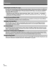
... reproduction of quality surround sound even at low volumes. 5.1 Channel Input By connecting components equipped with 5.1 channel analog output jacks. 5 Channels of Independent Amplification This receiver incorporates 5 independent 80 watt power amplifiers which enable high quality playback of Dolby Laboratories. "Dolby", "AC-3", "Pro Logic", " and double-D symbol are trademarks of Dolby...
... reproduction of quality surround sound even at low volumes. 5.1 Channel Input By connecting components equipped with 5.1 channel analog output jacks. 5 Channels of Independent Amplification This receiver incorporates 5 independent 80 watt power amplifiers which enable high quality playback of Dolby Laboratories. "Dolby", "AC-3", "Pro Logic", " and double-D symbol are trademarks of Dolby...
Owner's Manual
Page 5
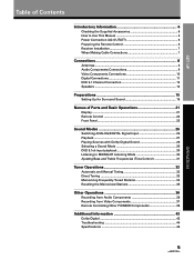
...Contents Introductory Information 6 Checking the Supplied Accessories 6 How to Use This Manual 6 Power Connection (AC OUTLET 6 Preparing the Remote Control 6 Receiver Installation 7 When Making Cable Connections 7 Connections 8 Antennas ...8 Audio Components Connections 9 Video Components Connections 10 Digital Connections 11 DVD 5.1 Channel Connection... Operations 36 Recording from Audio Components 36 Recording from Video Components 37 Remote Controlling Other PIONEER Components 38 Additional Information 43 Dolby Digital 43 Troubleshooting 44 Specifications 46 5 OPERATION
...Contents Introductory Information 6 Checking the Supplied Accessories 6 How to Use This Manual 6 Power Connection (AC OUTLET 6 Preparing the Remote Control 6 Receiver Installation 7 When Making Cable Connections 7 Connections 8 Antennas ...8 Audio Components Connections 9 Video Components Connections 10 Digital Connections 11 DVD 5.1 Channel Connection... Operations 36 Recording from Audio Components 36 Recording from Video Components 37 Remote Controlling Other PIONEER Components 38 Additional Information 43 Dolby Digital 43 Troubleshooting 44 Specifications 46 5 OPERATION

Owner's Manual
Page 6
...monitor is divided into two main sections : SET UP This section explains how to make the necessary connections from the receiver to the receiver's AC OUTLET jacks on and off. OPERATION This section provides complete information about operation of this section under the ... switched on or putting it in the operating range of connected components should not exceed 100W (0.8 A). Incorrect use different batteries together. Receiver operations described later in such hazards as blow dryers and irons to set . Indicates a steadily lit button, indicator, or display. ...
...monitor is divided into two main sections : SET UP This section explains how to make the necessary connections from the receiver to the receiver's AC OUTLET jacks on and off. OPERATION This section provides complete information about operation of this section under the ... switched on or putting it in the operating range of connected components should not exceed 100W (0.8 A). Incorrect use different batteries together. Receiver operations described later in such hazards as blow dryers and irons to set . Indicates a steadily lit button, indicator, or display. ...

Owner's Manual
Page 7
... cassette and/or video decks, move them farther away from the speakers. memo You can also control PIONEER components (and those made by the transformers in the receiver. SET UP Introductory Information Operating range of remote control unit Point the remote control toward the remote sensor...control signals to leave more than 8 inches of this unit to operate other PIONEER components simply by pointing the receiver's remote control directly at the remote sensor on the front panel of the receiver. When Making Cable Connections Be careful not to arrange cables in a manner ...
... cassette and/or video decks, move them farther away from the speakers. memo You can also control PIONEER components (and those made by the transformers in the receiver. SET UP Introductory Information Operating range of remote control unit Point the remote control toward the remote sensor...control signals to leave more than 8 inches of this unit to operate other PIONEER components simply by pointing the receiver's remote control directly at the remote sensor on the front panel of the receiver. When Making Cable Connections Be careful not to arrange cables in a manner ...
Owner's Manual
Page 9
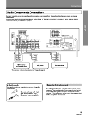
... switch power to standby and remove the power cord from the wall outlet when you experience noise, move the cassette deck farther away from the receiver. L Connect red plugs to R (right) and white plugs to insert completely. OPERA TION 9 R Be sure to L (left). If you make or change...noise may occur during playback of the audio signal. Cassette deck placement Depending on page 11 when making digital connections from the transformer in the receiver. Connect your DVD or LD player. Refer to connect the audio components. ANTENNA DIGITAL IN PCM/ OPT 1 OPT 2 FM UNBAL 75&#...
... switch power to standby and remove the power cord from the wall outlet when you experience noise, move the cassette deck farther away from the receiver. L Connect red plugs to R (right) and white plugs to insert completely. OPERA TION 9 R Be sure to L (left). If you make or change...noise may occur during playback of the audio signal. Cassette deck placement Depending on page 11 when making digital connections from the transformer in the receiver. Connect your DVD or LD player. Refer to connect the audio components. ANTENNA DIGITAL IN PCM/ OPT 1 OPT 2 FM UNBAL 75&#...
Owner's Manual
Page 11
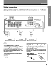
... connected as shown below . Digital audio cord Fiber-optic cables (or standard video cord) OPERA TION 11 The factory setting for Surround Sound" on this receiver. When you use optical digital input or output terminals, pull off the caps and insert the plugs. PARLEUR 6 ~ LESS THAN 8Ω /SPEAKER 6 ~ MOINS DE 8Ω...- You can select up to three of the following be assigned to "Setting Up for each of the digital inputs is then processed by the receiver through the digital input jacks.
... connected as shown below . Digital audio cord Fiber-optic cables (or standard video cord) OPERA TION 11 The factory setting for Surround Sound" on this receiver. When you use optical digital input or output terminals, pull off the caps and insert the plugs. PARLEUR 6 ~ LESS THAN 8Ω /SPEAKER 6 ~ MOINS DE 8Ω...- You can select up to three of the following be assigned to "Setting Up for each of the digital inputs is then processed by the receiver through the digital input jacks.
Owner's Manual
Page 15
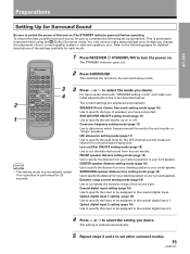
...LD 4 5 6 TV CONTROL TEST TONE 7 8 9 SURROUND ATT. 0 CD DISC FUNCTION DSP MODE MUTING CHANNEL SELECT LEVEL RECEIVER STANDBY/ON EFFECT MASTER VOLUME Î AV MULTI-CHANNEL RECEIVER REMOTE CONTROL UNIT 2 33 4 memo • The setting mode is automatically exited if no operation is particularly important when using...to determine which frequencies will be sent to specify the sub woofer as on . This is performed for each mode. 1 Press RECEIVER STANDBY/ON to make your current speaker system or add new speakers, etc.). This switches the remote to set up operations. ...
...LD 4 5 6 TV CONTROL TEST TONE 7 8 9 SURROUND ATT. 0 CD DISC FUNCTION DSP MODE MUTING CHANNEL SELECT LEVEL RECEIVER STANDBY/ON EFFECT MASTER VOLUME Î AV MULTI-CHANNEL RECEIVER REMOTE CONTROL UNIT 2 33 4 memo • The setting mode is automatically exited if no operation is particularly important when using...to determine which frequencies will be sent to specify the sub woofer as on . This is performed for each mode. 1 Press RECEIVER STANDBY/ON to make your current speaker system or add new speakers, etc.). This switches the remote to set up operations. ...
Owner's Manual
Page 16
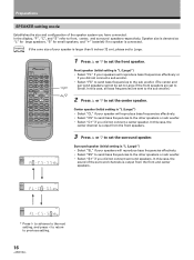
... MPX DIRECT CLASS .ACCESS DVD 1 2 3 LD 4 5 6 TV CONTROL TEST TONE 7 8 9 SURROUND ATT. 0 CD DISC FUNCTION DSP MODE MUTING CHANNEL SELECT LEVEL RECEIVER STANDBY/ON EFFECT MASTER VOLUME AV MULTI-CHANNEL RECEIVER REMOTE CONTROL UNIT Î 1 Press % or fi to previous setting. 16 Speaker size is denoted as ∗ "L" for large speakers, "S" for...
... MPX DIRECT CLASS .ACCESS DVD 1 2 3 LD 4 5 6 TV CONTROL TEST TONE 7 8 9 SURROUND ATT. 0 CD DISC FUNCTION DSP MODE MUTING CHANNEL SELECT LEVEL RECEIVER STANDBY/ON EFFECT MASTER VOLUME AV MULTI-CHANNEL RECEIVER REMOTE CONTROL UNIT Î 1 Press % or fi to previous setting. 16 Speaker size is denoted as ∗ "L" for large speakers, "S" for...
Owner's Manual
Page 20
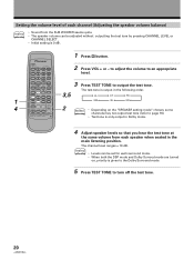
...TONE to an appropriate level. The channel level ranges ± 10 dB. FL CT FR 1 FUNCTION DSP MODE MUTING CHANNEL SELECT LEVEL SW SL SR 4 RECEIVER STANDBY/ON EFFECT MASTER VOLUME 2 memo • Depending on , priority is given to the Dolby Surround mode. 5 Press TEST TONE to page 16). Î...; AV MULTI-CHANNEL RECEIVER REMOTE CONTROL UNIT • Test tone is only output in Dolby mode. 4 Adjust speaker levels so that you hear the test tone at the same...
...TONE to an appropriate level. The channel level ranges ± 10 dB. FL CT FR 1 FUNCTION DSP MODE MUTING CHANNEL SELECT LEVEL SW SL SR 4 RECEIVER STANDBY/ON EFFECT MASTER VOLUME 2 memo • Depending on , priority is given to the Dolby Surround mode. 5 Press TEST TONE to page 16). Î...; AV MULTI-CHANNEL RECEIVER REMOTE CONTROL UNIT • Test tone is only output in Dolby mode. 4 Adjust speaker levels so that you hear the test tone at the same...
Owner's Manual
Page 21
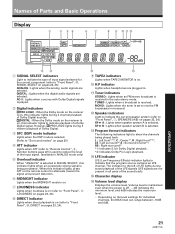
... display # Volume level display Displays the volume level. Tuner indicators STEREO : Lights when an FM stereo broadcast is selected. SP 3 A : Lights when speaker system A is received in the auto stereo mode. L : Left front*1*2, C : Center*1, R : Right front*1*2, LS : Left surround*1,S : Surround (mono)*2, RS : Right surround*1 *1: ...mode is selected. (Refer to "Surround modes" on pages 23, 24). @ # 9 TAPE2 indicators Lights when TAPE 2 MONITOR is received. DIGITAL : Lights when the digital audio signals are selected. Volume level is maintained even when the power is set to...
... display # Volume level display Displays the volume level. Tuner indicators STEREO : Lights when an FM stereo broadcast is selected. SP 3 A : Lights when speaker system A is received in the auto stereo mode. L : Left front*1*2, C : Center*1, R : Right front*1*2, LS : Left surround*1,S : Surround (mono)*2, RS : Right surround*1 *1: ...mode is selected. (Refer to "Surround modes" on pages 23, 24). @ # 9 TAPE2 indicators Lights when TAPE 2 MONITOR is received. DIGITAL : Lights when the digital audio signals are selected. Volume level is maintained even when the power is set to...
Owner's Manual
Page 22
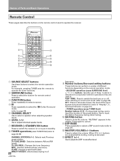
...Press to page 20). FREQ. For example, pressing TUNER sets the remote to operate the tuner functions. 2 SURROUND button Press to select the receiver for remote control operation. 3 FUNCTION button Press repeatedly to select a source. 4 Press repeatedly to select the (Dolby) Surround mode. (... 9 Number buttons/Surround setting buttons These buttons can perform a variety of different functions depending on the remote operation mode. • [RECEIVER operations (press SURROUND first buttons : Specific use to put in the display. When VOL (+/-) buttons are pressed while muting, muting is...
...Press to page 20). FREQ. For example, pressing TUNER sets the remote to operate the tuner functions. 2 SURROUND button Press to select the receiver for remote control operation. 3 FUNCTION button Press repeatedly to select a source. 4 Press repeatedly to select the (Dolby) Surround mode. (... 9 Number buttons/Surround setting buttons These buttons can perform a variety of different functions depending on the remote operation mode. • [RECEIVER operations (press SURROUND first buttons : Specific use to put in the display. When VOL (+/-) buttons are pressed while muting, muting is...
Owner's Manual
Page 23
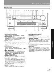
...the broadcast signal is in standby mode. (Please note that both speaker systems (A and B), press the buttons so that this receiver consumes a small amount of power (2.5 W) during the standby mode.) 3 CLASS button Press repeatedly to switch the preset station ...indicators on page 21). Names of Parts and Basic Operations Front Panel 1 2 3 4 56 7 8 9 0 - =~ !@# $ STANDBY STANDBY/ON VSX-D498 AUDIO/VIDEO MULTI-CHANNEL RECEIVER MPX CLASS MEMORY MODE - + STATION TUNING SELECT - + FREQUENCY DSP MODE SIGNAL SELECT MIDNIGHT PHONES SPEAKERS A B BASS TREBLE - + - + LOUDNESS ...
...the broadcast signal is in standby mode. (Please note that both speaker systems (A and B), press the buttons so that this receiver consumes a small amount of power (2.5 W) during the standby mode.) 3 CLASS button Press repeatedly to switch the preset station ...indicators on page 21). Names of Parts and Basic Operations Front Panel 1 2 3 4 56 7 8 9 0 - =~ !@# $ STANDBY STANDBY/ON VSX-D498 AUDIO/VIDEO MULTI-CHANNEL RECEIVER MPX CLASS MEMORY MODE - + STATION TUNING SELECT - + FREQUENCY DSP MODE SIGNAL SELECT MIDNIGHT PHONES SPEAKERS A B BASS TREBLE - + - + LOUDNESS ...
Owner's Manual
Page 24
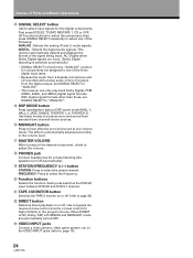
...is fixed in the "ANALOG" position for private listening (the speakers turn off . With digital signal formats other than these modes to bypass the receiver's tone control circuitry or level control for the digital components. First press DVD/LD, TV/SAT, MD/TAPE 1, CD or VCR (& Function...the three digital input jacks. • Because the audio from standard (two channel) stereo sources. # MIDNIGHT button Press to "ANALOG". • This receiver can only play back Dolby Digital, PCM (32kHz, 44kHz, and 48kHz),digital signal formats. to the VIDEO INPUT jacks (refer to select the frequency. &...
...is fixed in the "ANALOG" position for private listening (the speakers turn off . With digital signal formats other than these modes to bypass the receiver's tone control circuitry or level control for the digital components. First press DVD/LD, TV/SAT, MD/TAPE 1, CD or VCR (& Function...the three digital input jacks. • Because the audio from standard (two channel) stereo sources. # MIDNIGHT button Press to "ANALOG". • This receiver can only play back Dolby Digital, PCM (32kHz, 44kHz, and 48kHz),digital signal formats. to the VIDEO INPUT jacks (refer to select the frequency. &...

Owner's Manual
Page 25
Sound Modes This receiver incorporates two surround modes for enjoyment of a variety of wooden construction. You can identify Dolby Digital software by the or DOLBY DIGITAL AC-3 D I G I T A L marks. HALL 1 ...
Sound Modes This receiver incorporates two surround modes for enjoyment of a variety of wooden construction. You can identify Dolby Digital software by the or DOLBY DIGITAL AC-3 D I G I T A L marks. HALL 1 ...

Owner's Manual
Page 26
... audio from a karaoke microphone and LD recorded with analog audio only is not output from the digital output, set SIGNAL SELECT to "ANALOG". • This receiver can be switched to an analog or digital input signal by pressing the SIGNAL SELECT button. 1 Press SIGNAL SELECT on the front panel to select...
... audio from a karaoke microphone and LD recorded with analog audio only is not output from the digital output, set SIGNAL SELECT to "ANALOG". • This receiver can be switched to an analog or digital input signal by pressing the SIGNAL SELECT button. 1 Press SIGNAL SELECT on the front panel to select...
Owner's Manual
Page 27
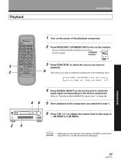
...3 LD 4 5 6 TV CONTROL TEST TONE 7 8 9 SURROUND ATT. 0 CD DISC FUNCTION DSP MODE MUTING CHANNEL SELECT LEVEL RECEIVER STANDBY/ON EFFECT MASTER VOLUME Î AV MULTI-CHANNEL RECEIVER REMOTE CONTROL UNIT 1 Turn on the power of --- FREQ. The source you want to -10 dB from the level displayed. 27...on page 26.) 5 Start playback of the component you want to playback is displayed in the range of the playback component. 2 Press RECEIVER STANDBY/ON to turn on the channel level setting, the MAX volume level may differ 0 to playback. dB (MIN) to "Switching ANALOG...
...3 LD 4 5 6 TV CONTROL TEST TONE 7 8 9 SURROUND ATT. 0 CD DISC FUNCTION DSP MODE MUTING CHANNEL SELECT LEVEL RECEIVER STANDBY/ON EFFECT MASTER VOLUME Î AV MULTI-CHANNEL RECEIVER REMOTE CONTROL UNIT 1 Turn on the power of --- FREQ. The source you want to -10 dB from the level displayed. 27...on page 26.) 5 Start playback of the component you want to playback is displayed in the range of the playback component. 2 Press RECEIVER STANDBY/ON to turn on the channel level setting, the MAX volume level may differ 0 to playback. dB (MIN) to "Switching ANALOG...
Owner's Manual
Page 28
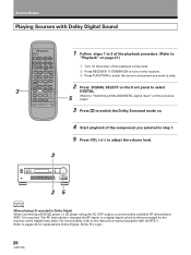
... Dolby Digital When connecting a DVD/LD player or LD player using the AC-3 RF output, a commercially available RF demodulator (RFD-1) is then processed by the receiver at the digital input jacks. TUNER MPX DIRECT CLASS .ACCESS DVD 1 2 3 LD 4 5 6 TV CONTROL TEST TONE 7 8 9 SURROUND ATT. 0 ...to 3 of the playback procedure. (Refer to "Playback" on page 27.) 1 Turn on the power of the playback component. 2 Press RECEIVER STADBY/ON to turn on the receiver. 3 Press FUNCTION to select the source component you want to play. 2 5 Press SIGNAL SELECT on the front panel to select DIGITAL....
... Dolby Digital When connecting a DVD/LD player or LD player using the AC-3 RF output, a commercially available RF demodulator (RFD-1) is then processed by the receiver at the digital input jacks. TUNER MPX DIRECT CLASS .ACCESS DVD 1 2 3 LD 4 5 6 TV CONTROL TEST TONE 7 8 9 SURROUND ATT. 0 ...to 3 of the playback procedure. (Refer to "Playback" on page 27.) 1 Turn on the power of the playback component. 2 Press RECEIVER STADBY/ON to turn on the receiver. 3 Press FUNCTION to select the source component you want to play. 2 5 Press SIGNAL SELECT on the front panel to select DIGITAL....
Owner's Manual
Page 29
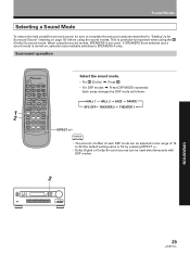
... DIRECT CLASS .ACCESS DVD 1 2 3 LD 4 5 6 TV CONTROL TEST TONE 7 8 9 SURROUND ATT. 0 CD DISC FUNCTION DSP MODE MUTING CHANNEL SELECT LEVEL RECEIVER STANDBY/ON EFFECT MASTER VOLUME Î AV MULTI-CHANNEL RECEIVER REMOTE CONTROL UNIT Select the sound mode. • For (Dolby) \ Press • For DSP modes \ Press DSP MODE repeatedly Each press...
... DIRECT CLASS .ACCESS DVD 1 2 3 LD 4 5 6 TV CONTROL TEST TONE 7 8 9 SURROUND ATT. 0 CD DISC FUNCTION DSP MODE MUTING CHANNEL SELECT LEVEL RECEIVER STANDBY/ON EFFECT MASTER VOLUME Î AV MULTI-CHANNEL RECEIVER REMOTE CONTROL UNIT Select the sound mode. • For (Dolby) \ Press • For DSP modes \ Press DSP MODE repeatedly Each press...


