Operating Instructions
Page 3
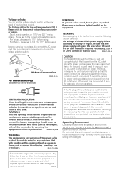
...(such as a lighted candle) on 127 V and 220 V mains voltage. Voltage selector You can find the voltage selector switch on the rear panel. D3-4-2-1-7a_A_En WARNING Before plugging in case of the area where this unit will need to high humidity or direct sunlight (or strong artificial ... service personnel. To prevent fire hazard, the openings should be used meets the required voltage (e.g., 230 V or 120 V) written on the rear panel of the available power supply differs according to change the voltage selector switch. To prevent a fire or shock hazard, do not place any ...
...(such as a lighted candle) on 127 V and 220 V mains voltage. Voltage selector You can find the voltage selector switch on the rear panel. D3-4-2-1-7a_A_En WARNING Before plugging in case of the area where this unit will need to high humidity or direct sunlight (or strong artificial ... service personnel. To prevent fire hazard, the openings should be used meets the required voltage (e.g., 230 V or 120 V) written on the rear panel of the available power supply differs according to change the voltage selector switch. To prevent a fire or shock hazard, do not place any ...
Operating Instructions
Page 17
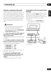
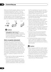
See the manuals that came with your TV or monitor. This only needs to be done if you made the rear panel connections. • Push down on your TV and source component to the following defaults: • COMPONENT - 1 - S - Use a three-way component video ... 2 - DVR See Assigning the component video inputs on page 58 for the connection. 2 If necessary, assign the component video inputs to the front panel video terminal Front video connections are compatible with progressive-scan video. Hook them up 04 Using the component video jacks Component video should deliver superior...
See the manuals that came with your TV or monitor. This only needs to be done if you made the rear panel connections. • Push down on your TV and source component to the following defaults: • COMPONENT - 1 - S - Use a three-way component video ... 2 - DVR See Assigning the component video inputs on page 58 for the connection. 2 If necessary, assign the component video inputs to the front panel video terminal Front video connections are compatible with progressive-scan video. Hook them up 04 Using the component video jacks Component video should deliver superior...
Operating Instructions
Page 20
... by other . • To achieve the best possible surround sound, install your speakers as earthquakes. • Make sure no exposed speaker wire is touching the rear panel, this may cause the receiver to turn off automatically. 20 En Some are designed to be floorstanding, while others should be placed near the TV...
... by other . • To achieve the best possible surround sound, install your speakers as earthquakes. • Make sure no exposed speaker wire is touching the rear panel, this may cause the receiver to turn off automatically. 20 En Some are designed to be floorstanding, while others should be placed near the TV...
Operating Instructions
Page 54
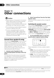
...Do not allow any contact between 6 Ω to 16 Ω (please see Switching the speaker impedance on the front panel to the (surround back) B speaker terminals on the rear panel. Note 1 • The subwoofer output depends on the settings you can use the speakers connected to select a speaker system... the SPEAKERS button. Switching the speaker system If you make with an impedance of speakers to the surround back speaker terminals on the rear panel to listen to use speakers with this . Sound is output from the two speakers connected to speaker system B (only stereo playback ...
...Do not allow any contact between 6 Ω to 16 Ω (please see Switching the speaker impedance on the front panel to the (surround back) B speaker terminals on the rear panel. Note 1 • The subwoofer output depends on the settings you can use the speakers connected to select a speaker system... the SPEAKERS button. Switching the speaker system If you make with an impedance of speakers to the surround back speaker terminals on the rear panel to listen to use speakers with this . Sound is output from the two speakers connected to speaker system B (only stereo playback ...
Operating Instructions
Page 61
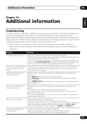
... Français Italiano Nederlands Español Chapter 14: Additional information Troubleshooting Incorrect operations are often mistaken for your nearest Pioneer authorized independent service company to carry out repair work. • If the unit does not operate normally due to external effects...; Make sure the subwoofer is incorrect. independent service company. Make sure you are no loose strands of speaker wire touching the rear panel. Problem The power does not turn muting off and the power indicator switch the receiver back on using the wrong voltage setting....
... Français Italiano Nederlands Español Chapter 14: Additional information Troubleshooting Incorrect operations are often mistaken for your nearest Pioneer authorized independent service company to carry out repair work. • If the unit does not operate normally due to external effects...; Make sure the subwoofer is incorrect. independent service company. Make sure you are no loose strands of speaker wire touching the rear panel. Problem The power does not turn muting off and the power indicator switch the receiver back on using the wrong voltage setting....
Service Manual
Page 109
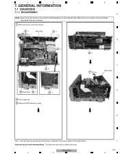
... described here are common. 1 Remove the top cover (five screws). 2 ×3 Heat Sink 5 ×1 B 4 ×3 6 ×1 2 ×2 7 Pull up C Rear Panel D 3 Push Rivet 2 ×1 2 ×1 4 Cut 3 cable ties. 5 Remove PCB holder(one screw). VSX-816-K 5 6 7 F 109 8 GENERAL INFORMATION 7.1 DIAGNOSIS 7.1.1 DISASSEMBLY 8 A Note: Even if the unit shown in the photos and illustrations in this manual...
... described here are common. 1 Remove the top cover (five screws). 2 ×3 Heat Sink 5 ×1 B 4 ×3 6 ×1 2 ×2 7 Pull up C Rear Panel D 3 Push Rivet 2 ×1 2 ×1 4 Cut 3 cable ties. 5 Remove PCB holder(one screw). VSX-816-K 5 6 7 F 109 8 GENERAL INFORMATION 7.1 DIAGNOSIS 7.1.1 DISASSEMBLY 8 A Note: Even if the unit shown in the photos and illustrations in this manual...
Service Manual
Page 110
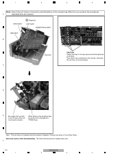
Heat-sink caution when disassembling : The Heat-sink becomes hot; F 110 VSX-816-K 1 2 3 4 1 2 3 4 Note: Even if the unit shown in the photos and illustrations in the rear panel should be connected to the chassis, otherwise the unit may differ from Rear Panel. TRANS Assy. MAIN ASSY 8 Diagnosis DSP ASSY POWER PACK ASSY USB ASSY B Heat Sink CAUTION...
Heat-sink caution when disassembling : The Heat-sink becomes hot; F 110 VSX-816-K 1 2 3 4 1 2 3 4 Note: Even if the unit shown in the photos and illustrations in the rear panel should be connected to the chassis, otherwise the unit may differ from Rear Panel. TRANS Assy. MAIN ASSY 8 Diagnosis DSP ASSY POWER PACK ASSY USB ASSY B Heat Sink CAUTION...


