Owner's Manual
Page 6
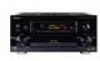
Table of Contents AC Power Cord 29 Features 5 AC Outlet [switched 100 W max 29 Before You Start 8 Checking the Supplied Accessories 8 Preparing the Remote Control 8 Loading the batteries 8 Remote Control Battery Alarm 8 The Touch Pen & Lock 9 Remote Control Cushions 9 Operating range of remote control unit 9 ...
Table of Contents AC Power Cord 29 Features 5 AC Outlet [switched 100 W max 29 Before You Start 8 Checking the Supplied Accessories 8 Preparing the Remote Control 8 Loading the batteries 8 Remote Control Battery Alarm 8 The Touch Pen & Lock 9 Remote Control Cushions 9 Operating range of remote control unit 9 ...

Owner's Manual
Page 8
Before You Start Checking the Supplied Accessories Please check that apply in the operating range or if the alarm sounds (see p. 10-11). Remote Control Battery Alarm When the batteries get an average of 1-3 months of power due to the LCD display so please use alkaline...batteries together. • Insert the plus and minus sides of batteries may have different voltages. SIZE AA, LR6 8 Observe the following supplied accessories. NOTE: After replacing the batteries, the touch panel will appear on individual use different batteries together. • When disposing of ...
Before You Start Checking the Supplied Accessories Please check that apply in the operating range or if the alarm sounds (see p. 10-11). Remote Control Battery Alarm When the batteries get an average of 1-3 months of power due to the LCD display so please use alkaline...batteries together. • Insert the plus and minus sides of batteries may have different voltages. SIZE AA, LR6 8 Observe the following supplied accessories. NOTE: After replacing the batteries, the touch panel will appear on individual use different batteries together. • When disposing of ...
Owner's Manual
Page 15
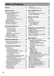
... ] Digital-6 [ VCR2 ] Digital-7 [ CD-R ] RF IN [ DVD/LD ] [Return] 1 Turn on the receiver and your TV, use any other power cord than the one that came with this receiver). 2 Press the POWER ON/OFF button to put the receiver in the first diagram on your TV (if it . The SYSTEM SETUP menu... doesn't, refer to page 13 to make sure you did not hook up the Main Unit Quick Start Guide Part1 QUICK START GUIDE 1 Connect the supplied AC power cord to the back of the main unit and plug the other end into a wall outlet (don't use the 5∞ buttons to your TV...
... ] Digital-6 [ VCR2 ] Digital-7 [ CD-R ] RF IN [ DVD/LD ] [Return] 1 Turn on the receiver and your TV, use any other power cord than the one that came with this receiver). 2 Press the POWER ON/OFF button to put the receiver in the first diagram on your TV (if it . The SYSTEM SETUP menu... doesn't, refer to page 13 to make sure you did not hook up the Main Unit Quick Start Guide Part1 QUICK START GUIDE 1 Connect the supplied AC power cord to the back of the main unit and plug the other end into a wall outlet (don't use the 5∞ buttons to your TV...
Owner's Manual
Page 23
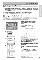
...TAPE/MD) Recorder 2 (CD-R/TAPE/MD) memo Don't hook up to an input other than PHONO. 7 Audio cords Use audio cords (not supplied) to connect the audio components. If your turntable has a phono pre-amplifier (most do not) please hook it to the SIGNAL GND terminal. ...IN PLAY 3 IN OUT (CD) REC TAPE2 MONITOR 2 IN (TV) IN PLAY 1 IN (DVD /LD) 2RF IN (DVD /LD) (For LD) ASSIGNABLE FRONT R SURROUND R AUDIO POWER AMP R L IN FRONT L R L CENTER 1 (Single) R R SUB W. PRE OUT 2 SURROUND L SURROUND BACK L (Single) CENTER SURROUND BACK L (Single) CONTROL IN MULTIROOM &...
...TAPE/MD) Recorder 2 (CD-R/TAPE/MD) memo Don't hook up to an input other than PHONO. 7 Audio cords Use audio cords (not supplied) to connect the audio components. If your turntable has a phono pre-amplifier (most do not) please hook it to the SIGNAL GND terminal. ...IN PLAY 3 IN OUT (CD) REC TAPE2 MONITOR 2 IN (TV) IN PLAY 1 IN (DVD /LD) 2RF IN (DVD /LD) (For LD) ASSIGNABLE FRONT R SURROUND R AUDIO POWER AMP R L IN FRONT L R L CENTER 1 (Single) R R SUB W. PRE OUT 2 SURROUND L SURROUND BACK L (Single) CENTER SURROUND BACK L (Single) CONTROL IN MULTIROOM &...

Owner's Manual
Page 27
...PHONO IN R AUDIO L S400 7 (CD-R/ CD TAPE1 IN /MD) IN R 6 (VCR2) IN R L R 5 OUT (VCR1 REC /DVR) IN CD-R/ TAPE1 OUT (AUDIO) AUDIO POWER AMP L IN FRONT L CENTER CONTROL IN MULTIROOM & SOURCE DVD /LD IN TV IN SAT IN OUT VCR1 MONITOR OUT OUT IN IN IN OUT DVD...best reception. Before making or changing the connections, switch off the power and disconnect the power cord from digital cables such as shown below. PREPARATION PREPARATION Connecting Your Equipment Connecting the Radio Antennas Connect the supplied FM wire antenna and the AM loop antenna to the ANTENNA ...
...PHONO IN R AUDIO L S400 7 (CD-R/ CD TAPE1 IN /MD) IN R 6 (VCR2) IN R L R 5 OUT (VCR1 REC /DVR) IN CD-R/ TAPE1 OUT (AUDIO) AUDIO POWER AMP L IN FRONT L CENTER CONTROL IN MULTIROOM & SOURCE DVD /LD IN TV IN SAT IN OUT VCR1 MONITOR OUT OUT IN IN IN OUT DVD...best reception. Before making or changing the connections, switch off the power and disconnect the power cord from digital cables such as shown below. PREPARATION PREPARATION Connecting Your Equipment Connecting the Radio Antennas Connect the supplied FM wire antenna and the AM loop antenna to the ANTENNA ...

Owner's Manual
Page 29
... Your Speakers Proper speaker placement is essential to realize the best sound from the wall socket when not in regular use any other power cord than the one supplied with high power consumption such as heaters, irons, or television sets to the AC OUTLET in order to avoid overheating and fire risk. AC... center channel is turned on vacation. Make sure all speakers are just a rough guide, for more details see page 109. AC Outlet [switched 100 W max] Power supplied through this unit's STANDBY/ON button.
... Your Speakers Proper speaker placement is essential to realize the best sound from the wall socket when not in regular use any other power cord than the one supplied with high power consumption such as heaters, irons, or television sets to the AC OUTLET in order to avoid overheating and fire risk. AC... center channel is turned on vacation. Make sure all speakers are just a rough guide, for more details see page 109. AC Outlet [switched 100 W max] Power supplied through this unit's STANDBY/ON button.
Owner's Manual
Page 31
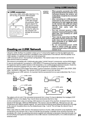
...the components form an open ended chain (fig. 1), or a tree (fig. 2). Forcing the cable into the connector. Check the operating instructions supplied with the component). • You can connect several i.LINKequipped components together in the same way. When setting up an i.LINK network, it's ... the connector on . Creating an i.LINK Network memo • When properly connected, the i.LINK plug will snap into the connector will when the power is on with i.LINK Audio (also called "A & M Protocol") components, such as a DVD recorder or DV camcorder), or an i.LINK-equipped...
...the components form an open ended chain (fig. 1), or a tree (fig. 2). Forcing the cable into the connector. Check the operating instructions supplied with the component). • You can connect several i.LINKequipped components together in the same way. When setting up an i.LINK network, it's ... the connector on . Creating an i.LINK Network memo • When properly connected, the i.LINK plug will snap into the connector will when the power is on with i.LINK Audio (also called "A & M Protocol") components, such as a DVD recorder or DV camcorder), or an i.LINK-equipped...

Owner's Manual
Page 35
...monitor. 13 MULTI-ROOM & SOURCE REMOTE IN terminals (see p.76. 18 AC IN (Power In) Hook up the power cord to this terminal. 19 AC outlet (Switched 100 W max.) Hook up an external component to the power supply of this receiver. The A system is fed by the surround and surround back speakers. ...OUTLET AC IN SPEAKERS ª ı· L R 14 15 17 18 11 CONTROL IN/OUT terminal You can use this jack to hook up other PIONEER equipment, with a CONTROL terminal, so that you can control them all pointing the remote control(s) at one that has the possibility on this receiver A & ...
...monitor. 13 MULTI-ROOM & SOURCE REMOTE IN terminals (see p.76. 18 AC IN (Power In) Hook up the power cord to this terminal. 19 AC outlet (Switched 100 W max.) Hook up an external component to the power supply of this receiver. The A system is fed by the surround and surround back speakers. ...OUTLET AC IN SPEAKERS ª ı· L R 14 15 17 18 11 CONTROL IN/OUT terminal You can use this jack to hook up other PIONEER equipment, with a CONTROL terminal, so that you can control them all pointing the remote control(s) at one that has the possibility on this receiver A & ...

Owner's Manual
Page 113
...The i.LINK source selected for the main room has also been selected as digital or analog. • Connect the POWER AMP IN terminals to the front channel pre outs using the supplied U-shaped connectors (p.34). • Connect the front speakers to be affecting the environment and switch them off if ... OSD during auto setup or memos on page 16-18. • Check for household appliances (air conditioner, fridge, fan, etc.) that connect the POWER AMP IN terminals to the front channel pre outs are not connected. • The front speakers are connected to the B speaker system jack. •...
...The i.LINK source selected for the main room has also been selected as digital or analog. • Connect the POWER AMP IN terminals to the front channel pre outs using the supplied U-shaped connectors (p.34). • Connect the front speakers to be affecting the environment and switch them off if ... OSD during auto setup or memos on page 16-18. • Check for household appliances (air conditioner, fridge, fan, etc.) that connect the POWER AMP IN terminals to the front channel pre outs are not connected. • The front speakers are connected to the B speaker system jack. •...

Owner's Manual
Page 115
...Adjust the direction and position for best reception. • Connect an additional internal or external AM antenna (see p.20). • Connect the POWER AMP IN terminals to the front channel pre outs using an analog source, the signal is too strong. A DVD-A source connected to MULTI CH... MULTI CH IN button (p.59). Other audio problems Subwoofer output is not connected. • 2 RF and/or digital cables are using the supplied U-shaped connectors (p.34). The OVER indicator is poorly positioned. • Weak radio signals. Noise or hum can be FM broadcasts selected automatically....
...Adjust the direction and position for best reception. • Connect an additional internal or external AM antenna (see p.20). • Connect the POWER AMP IN terminals to the front channel pre outs using an analog source, the signal is too strong. A DVD-A source connected to MULTI CH... MULTI CH IN button (p.59). Other audio problems Subwoofer output is not connected. • 2 RF and/or digital cables are using the supplied U-shaped connectors (p.34). The OVER indicator is poorly positioned. • Weak radio signals. Noise or hum can be FM broadcasts selected automatically....


