Owner's Manual
Page 1
AUDIO/VIDEO MULTI-CHANNEL RECEIVER VSX-41 Operating Instructions
AUDIO/VIDEO MULTI-CHANNEL RECEIVER VSX-41 Operating Instructions
Owner's Manual
Page 4
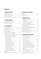
... terminals 20 A and B speaker systems 20 Hints on speaker placement 20 Connecting additional amplifiers 22 AC outlet 23 Operating other Pioneer components .......... 23 4 Controls and displays Front panel 24 Display 25 Remote control 27 5 Playing sources Introduction to Sound Modes ... controls 34 Playing other sources 34 Selecting the multichannel analog inputs .... 35 Using Re-Equalization 35 6 Setting up your receiver Choosing your receiver setup 36 Speaker setting 37 Surround back speaker setting 37 6.1 channel setting 38 Subwoofer setting 38 Crossover frequency setting 38...
... terminals 20 A and B speaker systems 20 Hints on speaker placement 20 Connecting additional amplifiers 22 AC outlet 23 Operating other Pioneer components .......... 23 4 Controls and displays Front panel 24 Display 25 Remote control 27 5 Playing sources Introduction to Sound Modes ... controls 34 Playing other sources 34 Selecting the multichannel analog inputs .... 35 Using Re-Equalization 35 6 Setting up your receiver Choosing your receiver setup 36 Speaker setting 37 Surround back speaker setting 37 6.1 channel setting 38 Subwoofer setting 38 Crossover frequency setting 38...

Owner's Manual
Page 6
... disposing of used batteries, please comply with governmental regulations or environmental public instruction's rules that is emitting infrared rays. • The receiver is located near a device that apply in your country or area. Operating range of remote control unit The remote control may not work...Making cable connections Make sure not to leave more than 8 inches (20 cm.) of space above the receiver. 01 Before you start Checking what's in the box Please check that you've received the following supplied accessories: • AM loop antenna • FM wire antenna • Dry cell...
... disposing of used batteries, please comply with governmental regulations or environmental public instruction's rules that is emitting infrared rays. • The receiver is located near a device that apply in your country or area. Operating range of remote control unit The remote control may not work...Making cable connections Make sure not to leave more than 8 inches (20 cm.) of space above the receiver. 01 Before you start Checking what's in the box Please check that you've received the following supplied accessories: • AM loop antenna • FM wire antenna • Dry cell...

Owner's Manual
Page 7
The surround sound you get from one disc, all of them being there'. This receiver will automatically decode Dolby Digital, DTS, or Dolby Surround DVD-Video discs, according to your system. 5 minute guide 02 Introduction to home theater You are ...explained in Playing sources, starting on the source and the sound settings of the receiver. Home theater refers to the use . In most cases, you 're in the middle of 'being sent to soundtracks. Depending on the DVD, you can...
The surround sound you get from one disc, all of them being there'. This receiver will automatically decode Dolby Digital, DTS, or Dolby Surround DVD-Video discs, according to your system. 5 minute guide 02 Introduction to home theater You are ...explained in Playing sources, starting on the source and the sound settings of the receiver. Home theater refers to the use . In most cases, you 're in the middle of 'being sent to soundtracks. Depending on the DVD, you can...
Owner's Manual
Page 8
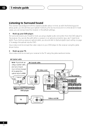
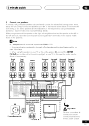
02 5 minute guide Listening to Surround Sound This receiver was designed with the easiest possible setup in no time at all. Use a video cord to connect your TV. DIGITAL OUT VIDEO OUT S STANDBY/ON 41 ¡¢ 0 7 8 Î 3 DVD PLAYER DVD player Video cord DIGITAL IN OPT ...ASSIGNABLE (DVD/ LD)¥ (TV/ SAT) ¥ This receiver DVD IN / LD FRONT IN D V D ANTENNA5.1CIN H REC INPUT CD-R AM...
02 5 minute guide Listening to Surround Sound This receiver was designed with the easiest possible setup in no time at all. Use a video cord to connect your TV. DIGITAL OUT VIDEO OUT S STANDBY/ON 41 ¡¢ 0 7 8 Î 3 DVD PLAYER DVD player Video cord DIGITAL IN OPT ...ASSIGNABLE (DVD/ LD)¥ (TV/ SAT) ¥ This receiver DVD IN / LD FRONT IN D V D ANTENNA5.1CIN H REC INPUT CD-R AM...
Owner's Manual
Page 9
... vary. Also make sure the positive and negative (+/-) terminals on the receiver match those on the speakers. • Use speakers with just two stereo speakers (the front speakers in the manner shown below. VIDEO SAT) SURROUND MONITOR (...
... vary. Also make sure the positive and negative (+/-) terminals on the receiver match those on the speakers. • Use speakers with just two stereo speakers (the front speakers in the manner shown below. VIDEO SAT) SURROUND MONITOR (...

Owner's Manual
Page 11
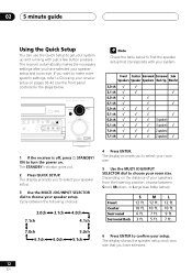
... page if you're unsure about the settings. 6 Play a DVD, and adjust the volume to do this case, the listening mode must be set the receiver to the DVD input. 5 Press QUICK SETUP on the remote control to set -see page 32-33 if you need to specify your speaker setup... and your room size. Depending on , followed by your DVD player, your subwoofer and the TV. 5 minute guide 02 4 Plug in the receiver's display, indicating that came with the TV if you don't know how to your liking. Make sure you've set to Standard (it on your...
... page if you're unsure about the settings. 6 Play a DVD, and adjust the volume to do this case, the listening mode must be set the receiver to the DVD input. 5 Press QUICK SETUP on the remote control to set -see page 32-33 if you need to specify your speaker setup... and your room size. Depending on , followed by your DVD player, your subwoofer and the TV. 5 minute guide 02 4 Plug in the receiver's display, indicating that came with the TV if you don't know how to your liking. Make sure you've set to Standard (it on your...
Owner's Manual
Page 12
...3.0ch 7.1ch 3.1ch 4.0ch 4.1ch 4 Press ENTER. If you to select your speaker setup. 3 Use the MULTI JOG/INPUT SELECTOR dial to choose your receiver setup on pages 36-42 Use the front panel controls for the steps below ). The display prompts you want to make more specific settings, refer... goes out. 2 Press QUICK SETUP. Depending on the distance of your speaker setup and room size. M 12 ft. 10 ft. 7 ft. 5 ft. The receiver automatically makes the necessary settings after you to select your room size. 5 Use the MULTI JOG/INPUT SELECTOR dial to choose your setup. Front Center...
...3.0ch 7.1ch 3.1ch 4.0ch 4.1ch 4 Press ENTER. If you to select your speaker setup. 3 Use the MULTI JOG/INPUT SELECTOR dial to choose your receiver setup on pages 36-42 Use the front panel controls for the steps below ). The display prompts you want to make more specific settings, refer... goes out. 2 Press QUICK SETUP. Depending on the distance of your speaker setup and room size. M 12 ft. 10 ft. 7 ft. 5 ft. The receiver automatically makes the necessary settings after you to select your room size. 5 Use the MULTI JOG/INPUT SELECTOR dial to choose your setup. Front Center...
Owner's Manual
Page 13
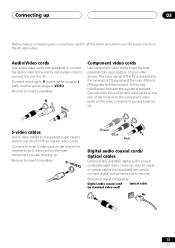
...S-video jack on the video component you are hooking up . Digital audio coaxial cord (or standard video cord) Optical cable 13 En In this receiver. Be sure to insert completely. Connect from the AC wall outlet. R L VIDEO Component video cords Use component video cords to get the best...Before making or changing any connections, switch off the power and disconnect the power cord from the component video jacks on the rear of the receiver to the component video jacks on the video component you are hooking up . S-video cables Use S-video cables (not supplied) to get ...
...S-video jack on the video component you are hooking up . Digital audio coaxial cord (or standard video cord) Optical cable 13 En In this receiver. Be sure to insert completely. Connect from the AC wall outlet. R L VIDEO Component video cords Use component video cords to get the best...Before making or changing any connections, switch off the power and disconnect the power cord from the component video jacks on the rear of the receiver to the component video jacks on the video component you are hooking up . S-video cables Use S-video cables (not supplied) to get ...
Owner's Manual
Page 14
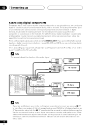
...but since some digital components only have an LD player, you can play 2 RF format LDs on the receiver). There are unsure about its input and output jacks. 14 En The arrows indicate the direction of matching... you need to coaxial input on your system. 03 Connecting up Connecting digital components The easiest way to hook up this receiver for example, the coaxial output from the AC wall outlet. ASSIGNABLE (DVD/ LD) IN ¥ CD (DVD/ ...of digital terminal, it is a matter of the audio signal. The VSX-41 has four digital inputs (two coaxial inputs and two optical inputs).
...but since some digital components only have an LD player, you can play 2 RF format LDs on the receiver). There are unsure about its input and output jacks. 14 En The arrows indicate the direction of matching... you need to coaxial input on your system. 03 Connecting up Connecting digital components The easiest way to hook up this receiver for example, the coaxial output from the AC wall outlet. ASSIGNABLE (DVD/ LD) IN ¥ CD (DVD/ ...of digital terminal, it is a matter of the audio signal. The VSX-41 has four digital inputs (two coaxial inputs and two optical inputs).
Owner's Manual
Page 15
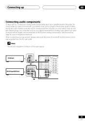
... for components that only play, you need to /from the AC wall outlet. When connecting your analog audio components (such as a cassette deck) to the receiver (a set of stereo inputs and a set of stereo outputs), but for more on digital connections. ANTENNA IN CD AM LOOP FM UNBAL IN 75 Ω...
... for components that only play, you need to /from the AC wall outlet. When connecting your analog audio components (such as a cassette deck) to the receiver (a set of stereo inputs and a set of stereo outputs), but for more on digital connections. ANTENNA IN CD AM LOOP FM UNBAL IN 75 Ω...
Owner's Manual
Page 16
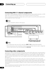
... connection. With digital video components (like a DVD player), you must use a separate component for the video signal, but in this receiver. Connecting video components Connect your digital components with analog audio connections (see the second illustration of the signal. The arrows indicate the direction...Connecting up Connecting DVD 7.1 channel components If you prefer to use one type of the connections shown on the rear of the receiver instead of the regular video jacks (see page 15). Make sure they are connecting only has one surround back channel output, ...
... connection. With digital video components (like a DVD player), you must use a separate component for the video signal, but in this receiver. Connecting video components Connect your digital components with analog audio connections (see the second illustration of the signal. The arrows indicate the direction...Connecting up Connecting DVD 7.1 channel components If you prefer to use one type of the connections shown on the rear of the receiver instead of the regular video jacks (see page 15). Make sure they are connecting only has one surround back channel output, ...

Owner's Manual
Page 18
.... FM UNBAL 75Ω 75 Ω coaxial cable FM ANTENNA To improve AM reception Connect a 15-18 feet length of vinyl-coated wire to the receiver. 03 Connecting up Connecting antennas Connect the AM loop antenna and the FM wire antenna as shown below ). Always make sure that gives the best... antenna. Antenna snap connectors Twist the exposed wire strands together and insert into the hole, then snap the connector shut. 3/8 in the direction that the receiver is switched off and unplugged from the wall outlet before making or changing any connections.
.... FM UNBAL 75Ω 75 Ω coaxial cable FM ANTENNA To improve AM reception Connect a 15-18 feet length of vinyl-coated wire to the receiver. 03 Connecting up Connecting antennas Connect the AM loop antenna and the FM wire antenna as shown below ). Always make sure that gives the best... antenna. Antenna snap connectors Twist the exposed wire strands together and insert into the hole, then snap the connector shut. 3/8 in the direction that the receiver is switched off and unplugged from the wall outlet before making or changing any connections.
Owner's Manual
Page 19
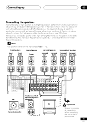
... LD)¥ S - Make sure you 're not using at least three speakers is recommended, and a complete setup is shown below . The receiver will vary. Front Speakers Front Left Front Right Center Speaker Center Surround Speakers Surround Left Surround Right Surround Back Speakers Surround Surround Back Left Back...complete setup of 8 Ω to the AC power source. 19 En Also make sure the positive and negative (+/-) terminals on the receiver match those on the left terminal. If you connect the speaker on the right to the right terminal and the speaker on the speakers...
... LD)¥ S - Make sure you 're not using at least three speakers is recommended, and a complete setup is shown below . The receiver will vary. Front Speakers Front Left Front Right Center Speaker Center Surround Speakers Surround Left Surround Right Surround Back Speakers Surround Surround Back Left Back...complete setup of 8 Ω to the AC power source. 19 En Also make sure the positive and negative (+/-) terminals on the receiver match those on the left terminal. If you connect the speaker on the right to the right terminal and the speaker on the speakers...
Owner's Manual
Page 20
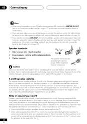
...the audio input jack on this case the center speaker shown is the main system supporting the full speaker setup. A and B speaker systems The receiver has two speaker systems: A and B. A is unnecessary. • If you are using magnetically shielded speakers to cut off as the center ... speaker terminal. Speaker terminals 1 Twist exposed wire strands together. 3/8 in the Surround back speaker setting (see illustration on stands to the receiver. Connect the positive wire to the right channel (+) terminal, and the negative wire to the active speakers so no sound will be placed...
...the audio input jack on this case the center speaker shown is the main system supporting the full speaker setup. A and B speaker systems The receiver has two speaker systems: A and B. A is unnecessary. • If you are using magnetically shielded speakers to cut off as the center ... speaker terminal. Speaker terminals 1 Twist exposed wire strands together. 3/8 in the Surround back speaker setting (see illustration on stands to the receiver. Connect the positive wire to the right channel (+) terminal, and the negative wire to the active speakers so no sound will be placed...
Owner's Manual
Page 22
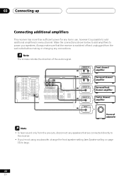
... amplifier Center channel amplifier Powered subwoofer • To hear sound only from the wall outlet before making or changing any speakers that the receiver is possible to add additional amplifiers to every channel. The arrows indicate the direction of the audio signal. Make the connections shown below ...to add amplifiers to large. 22 En Always make sure that are connected directly to the receiver. • If you're not using a subwoofer, change the front speaker setting (see Speaker setting on page 37) to power your speakers....
... amplifier Center channel amplifier Powered subwoofer • To hear sound only from the wall outlet before making or changing any speakers that the receiver is possible to add additional amplifiers to every channel. The arrows indicate the direction of the audio signal. Make the connections shown below ...to add amplifiers to large. 22 En Always make sure that are connected directly to the receiver. • If you're not using a subwoofer, change the front speaker setting (see Speaker setting on page 37) to power your speakers....
Owner's Manual
Page 23
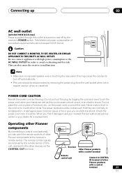
... to be disconnected by removing the power plug from the wall socket when not in order to malfunction. OUT CONTROL CONTROL IN OUT Receiver Other Pioneer products with a control terminal Remote control unit Connect to CONTROL IN terminal of this unit, and sent to the other...cord once in the cord or tie it damaged, ask your nearest Pioneer authorized service center or your hands are received by the receiver's POWER switch. This can cause a fire or give you find it with other Pioneer components at the receiver's remote sensor. POWER-CORD CAUTION Handle the power cord by tugging ...
... to be disconnected by removing the power plug from the wall socket when not in order to malfunction. OUT CONTROL CONTROL IN OUT Receiver Other Pioneer products with a control terminal Remote control unit Connect to CONTROL IN terminal of this unit, and sent to the other...cord once in the cord or tie it damaged, ask your nearest Pioneer authorized service center or your hands are received by the receiver's POWER switch. This can cause a fire or give you find it with other Pioneer components at the receiver's remote sensor. POWER-CORD CAUTION Handle the power cord by tugging ...
Owner's Manual
Page 24
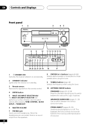
...VIDEO L AUDIO R 24 23 22 21 20 19 18 17 1 STANDBY/ON Switches the receiver between on or off. When the headphones are connected, there is in standby. 3 Remote sensor Receives the signals from the speakers. This bypasses the tone controls and channel levels for Standard decoding...between the various Pro Logic II options. STEREO/DIRECT (pages 30, 33) Switches direct playback on and standby. 2 STANDBY indicator Lights when the receiver is no sound output from the remote control. 4 ENTER button 5 MULTI JOG/INPUT SELECTOR dial The MULTI JOG/INPUT SELECTOR dial performs a number...
...VIDEO L AUDIO R 24 23 22 21 20 19 18 17 1 STANDBY/ON Switches the receiver between on or off. When the headphones are connected, there is in standby. 3 Remote sensor Receives the signals from the speakers. This bypasses the tone controls and channel levels for Standard decoding...between the various Pro Logic II options. STEREO/DIRECT (pages 30, 33) Switches direct playback on and standby. 2 STANDBY indicator Lights when the receiver is no sound output from the remote control. 4 ENTER button 5 MULTI JOG/INPUT SELECTOR dial The MULTI JOG/INPUT SELECTOR dial performs a number...
Owner's Manual
Page 25
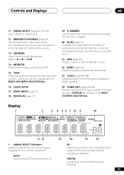
... 04 11 SIGNAL SELECT (pages 32, 35, 46) Use to select an input signal. 12 MIDNIGHT/LOUDNESS (page 33) Use Midnight when listening to receive a radio broadcast in mono. 22 BAND (page 43) Switches between AM and FM radio bands. 23 CLASS (pages 44-45) Switches between the three...= B = A+B 14 MONITOR Press to switch tape monitoring on the source, this button to make the fluorescent display (FL) dimmer or brighter. 20 Re-EQ (page 41) This feature compensates for the effect of reproducing sounds that have been originally processed for a large movie theater in a smaller room. 21 MPX (page 43...
... 04 11 SIGNAL SELECT (pages 32, 35, 46) Use to select an input signal. 12 MIDNIGHT/LOUDNESS (page 33) Use Midnight when listening to receive a radio broadcast in mono. 22 BAND (page 43) Switches between AM and FM radio bands. 23 CLASS (pages 44-45) Switches between the three...= B = A+B 14 MONITOR Press to switch tape monitoring on the source, this button to make the fluorescent display (FL) dimmer or brighter. 20 Re-EQ (page 41) This feature compensates for the effect of reproducing sounds that have been originally processed for a large movie theater in a smaller room. 21 MPX (page 43...

Owner's Manual
Page 26
...signal. 6 RE-EQ: Lights when Re-Equalization is detected. Depending on your level settings for smaller rooms. 7 DIRECT Lights when source direct playback is being received. 16 Master volume level Shows the overall volume level. ---dB indicates the minimum level, and -0dB indicates the maximum level. TUNED: Lights when a broadcast is... on, this lights to indicate decoding of a Dolby Digital signal. 4 2 PRO LOGIC II When the Standard mode of the receiver is on, this lights to indicate Pro Logic II decoding. 5 ATT Lights when INPUT ATT is used to attenuate (reduce) the level of the ...
...signal. 6 RE-EQ: Lights when Re-Equalization is detected. Depending on your level settings for smaller rooms. 7 DIRECT Lights when source direct playback is being received. 16 Master volume level Shows the overall volume level. ---dB indicates the minimum level, and -0dB indicates the maximum level. TUNED: Lights when a broadcast is... on, this lights to indicate decoding of a Dolby Digital signal. 4 2 PRO LOGIC II When the Standard mode of the receiver is on, this lights to indicate Pro Logic II decoding. 5 ATT Lights when INPUT ATT is used to attenuate (reduce) the level of the ...


