Operating Instructions
Page 1
AUDIO/VIDEO MULTI-CHANNEL RECEIVER VSX-21 Operating Instructions
AUDIO/VIDEO MULTI-CHANNEL RECEIVER VSX-21 Operating Instructions

Operating Instructions
Page 2
...interference to operate your model properly. Reorient or relocate the receiving antenna. - Consult the dealer or an experienced radio/TV technician for future reference. IMPORTANT NOTICE The serial number for this Pioneer product. The exclamation point within the product's enclosure that... interference will know how to radio communications. Increase the separation between the equipment and receiver. - This is for your security. Please read...
...interference to operate your model properly. Reorient or relocate the receiving antenna. - Consult the dealer or an experienced radio/TV technician for future reference. IMPORTANT NOTICE The serial number for this Pioneer product. The exclamation point within the product's enclosure that... interference will know how to radio communications. Increase the separation between the equipment and receiver. - This is for your security. Please read...
Operating Instructions
Page 4
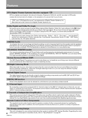
... Processing) surround mode allows you can enjoy a clearer sound. 5.1 Channel Input By connecting components equipped with 5.1 channel analog output jacks. 5 Channels of Independent Amplification This receiver incorporates 5 independent 100 watt power amplifiers which enable high quality playback of Digital Theater Systems, Inc. Connections can be directly output to transform your home...
... Processing) surround mode allows you can enjoy a clearer sound. 5.1 Channel Input By connecting components equipped with 5.1 channel analog output jacks. 5 Channels of Independent Amplification This receiver incorporates 5 independent 100 watt power amplifiers which enable high quality playback of Digital Theater Systems, Inc. Connections can be directly output to transform your home...
Operating Instructions
Page 5
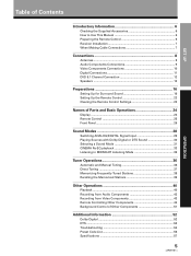
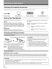
SET UP Table of Contents Introductory Information 6 Checking the Supplied Accessories 6 How to Use This Manual 6 Preparing the Remote Control 6 Receiver Installation 7 When Making Cable Connections 7 Connections 8 Antennas ...8 Audio Components Connections 9 Video Components Connections 10 Digital Connections 11 DVD 5.1 Channel Connection 12 Speakers 13 Preparations 16 ...
SET UP Table of Contents Introductory Information 6 Checking the Supplied Accessories 6 How to Use This Manual 6 Preparing the Remote Control 6 Receiver Installation 7 When Making Cable Connections 7 Connections 8 Antennas ...8 Audio Components Connections 9 Video Components Connections 10 Digital Connections 11 DVD 5.1 Channel Connection 12 Speakers 13 Preparations 16 ...
Operating Instructions
Page 6
...all of the following precautions. • Never use of the batteries properly according to your home entertainment center. Total power consumption of the receiver and supplied remote control. Power connection CAUTION! OPERATION This section provides complete information about operation of connected components should not exceed 100W (0.8 ... This manual is divided into two main sections : SET UP This section explains how to make the necessary connections from the receiver to the marks in the ON position. If not, the preset codes may be canceled and you will need to the...
...all of the following precautions. • Never use of the batteries properly according to your home entertainment center. Total power consumption of the receiver and supplied remote control. Power connection CAUTION! OPERATION This section provides complete information about operation of connected components should not exceed 100W (0.8 ... This manual is divided into two main sections : SET UP This section explains how to make the necessary connections from the receiver to the marks in the ON position. If not, the preset codes may be canceled and you will need to the...
Operating Instructions
Page 7
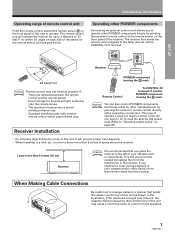
...the speakers. This will prevent noise caused by pointing the receiver's remote control directly at the remote sensor on the front panel of the receiver. OPERATION 7 memo You can also control PIONEER components (and those made by other manufacturers) by leakage ... your cassette and/ or video decks. Operating other PIONEER components Connecting an optional control cord allows you experience noise during playback of space above the receiver. Receiver Installation CONTROL OUT IN Receiver CONTROL IN OUT PIONEER component bearing the Î mark. When Making Cable...
...the speakers. This will prevent noise caused by pointing the receiver's remote control directly at the remote sensor on the front panel of the receiver. OPERATION 7 memo You can also control PIONEER components (and those made by other manufacturers) by leakage ... your cassette and/ or video decks. Operating other PIONEER components Connecting an optional control cord allows you experience noise during playback of space above the receiver. Receiver Installation CONTROL OUT IN Receiver CONTROL IN OUT PIONEER component bearing the Î mark. When Making Cable...
Operating Instructions
Page 9
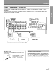
Refer to "Digital Connections" on where the cassette deck is caused by leakage flux from the transformer in the receiver. If you make or change connections. OPERATION 9 ANTENNA DIGITAL IN OPT 1 PCM/ /DTS FM UNBAL 75Ω OPT 2 DVD 5.1 CH INPUT OPT 3 SURROUND L SUBWOOFER ... switch power to standby and remove the power cord from the wall outlet when you experience noise, move the cassette deck farther away from the receiver. Connect your DVD or LD player. R Be sure to L (left). Cassette deck 7 Audio cords Use audio cords (not supplied) to connect the audio ...
Refer to "Digital Connections" on where the cassette deck is caused by leakage flux from the transformer in the receiver. If you make or change connections. OPERATION 9 ANTENNA DIGITAL IN OPT 1 PCM/ /DTS FM UNBAL 75Ω OPT 2 DVD 5.1 CH INPUT OPT 3 SURROUND L SUBWOOFER ... switch power to standby and remove the power cord from the wall outlet when you experience noise, move the cassette deck farther away from the receiver. Connect your DVD or LD player. R Be sure to L (left). Cassette deck 7 Audio cords Use audio cords (not supplied) to connect the audio ...

Operating Instructions
Page 10
...S-Video jacks on the rear panel, S, S1 and S2 S-video connection can make connections to this unit is possible by connecting the receiver to your TV monitor or video camera has an S-Video input, clearer picture reproduction is not designed to convert the format of the ...below. However, this unit using S-video cords (not supplied). R Be sure to VIDEO. Connections Video Components Connections • When connecting components, the receiver should be output from the S2 OUT. 10 7 Audio/Video cords Use audio/video cords (not supplied) to connect the video components and a video...
...S-Video jacks on the rear panel, S, S1 and S2 S-video connection can make connections to this unit is possible by connecting the receiver to your TV monitor or video camera has an S-Video input, clearer picture reproduction is not designed to convert the format of the ...below. However, this unit using S-video cords (not supplied). R Be sure to VIDEO. Connections Video Components Connections • When connecting components, the receiver should be output from the S2 OUT. 10 7 Audio/Video cords Use audio/video cords (not supplied) to connect the video components and a video...
Operating Instructions
Page 11
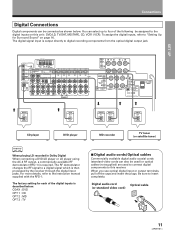
... cord) OPERATION 11 For more details, refer to insert completely. You can select up to four of the digital inputs is then processed by the receiver through the digital input jacks. The RF demodulator changes the RF signal to a digital signal which is described below . When you use optical digital input... digital audio coaxial cords (standard video cords can be assigned to the digital inputs on page 16. The factory setting for Surround Sound" on this receiver. Be sure to the instruction manual supplied with the RFD-1.
... cord) OPERATION 11 For more details, refer to insert completely. You can select up to four of the digital inputs is then processed by the receiver through the digital input jacks. The RF demodulator changes the RF signal to a digital signal which is described below . When you use optical digital input... digital audio coaxial cords (standard video cords can be assigned to the digital inputs on page 16. The factory setting for Surround Sound" on this receiver. Be sure to the instruction manual supplied with the RFD-1.
Operating Instructions
Page 16
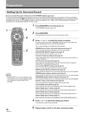
...attenuator setting mode (page 18) Use to specify the peak level for the LFE channel and the crossover network for 20 seconds. 4 Press RECEIVER to your front speaker. FRONT speaker distance setting mode (page 19) Use to specify the distance from your listening position to turn the power...optical digital input 3. To ensure the best possible surround sound, be assigned to the coaxial digital input. Optical digital input 3 setting (page 21) Use to specify the input to be sure to complete the following pages for detailed descriptions of the settings available for Surround Sound Be ...
...attenuator setting mode (page 18) Use to specify the peak level for the LFE channel and the crossover network for 20 seconds. 4 Press RECEIVER to your front speaker. FRONT speaker distance setting mode (page 19) Use to specify the distance from your listening position to turn the power...optical digital input 3. To ensure the best possible surround sound, be assigned to the coaxial digital input. Optical digital input 3 setting (page 21) Use to specify the input to be sure to complete the following pages for detailed descriptions of the settings available for Surround Sound Be ...
Operating Instructions
Page 21
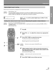
...CD VCR 1 TVCONTROL TUNER 2 3 Press TEST TONE to set for the component and the jack formerly selected is turned off the test tone. 21 memo • Levels can be adjusted without outputting the test tone by pressing CHANNEL LEVEL or CHANNEL SELECT . • Initial setting is only ...output in the following order. The test tone is possible. RECEIVER TV 1 Press . MUTING FQ TV FUNC + ENTER 2 Press VOL + or - memo • Initial setting is "TV". • You cannot assign the...
...CD VCR 1 TVCONTROL TUNER 2 3 Press TEST TONE to set for the component and the jack formerly selected is turned off the test tone. 21 memo • Levels can be adjusted without outputting the test tone by pressing CHANNEL LEVEL or CHANNEL SELECT . • Initial setting is only ...output in the following order. The test tone is possible. RECEIVER TV 1 Press . MUTING FQ TV FUNC + ENTER 2 Press VOL + or - memo • Initial setting is "TV". • You cannot assign the...

Operating Instructions
Page 22
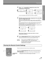
...component you how to control. SIGNAL SELECT ANALOG SP A dB 2 MULTI CONTROL DVD/LD TV/SAT CD VCR 1 TVCONTROL TUNER SIGNAL SELECT ANALOG SP A VCR 2 RECEIVER MD/TAPE DSP MODE MIDNIGHT dB 12 34 CH.SELECT TEST TONE ATT SIG.SELECT 56 7 8 CN.LEVEL 90 EFFECT +10 MEMU CLASS TV/VCR... FUNCTION DIRECT FL DIMMER To cancel the preset mode Press COMMANDER SET UP. RECEIVER TV MUTING FQ TV FUNC + ENTER - If your other components. FQ VOL VOL CHANNEL 1 Press COMMANDER SET UP and 1 at the same time to ...
...component you how to control. SIGNAL SELECT ANALOG SP A dB 2 MULTI CONTROL DVD/LD TV/SAT CD VCR 1 TVCONTROL TUNER SIGNAL SELECT ANALOG SP A VCR 2 RECEIVER MD/TAPE DSP MODE MIDNIGHT dB 12 34 CH.SELECT TEST TONE ATT SIG.SELECT 56 7 8 CN.LEVEL 90 EFFECT +10 MEMU CLASS TV/VCR... FUNCTION DIRECT FL DIMMER To cancel the preset mode Press COMMANDER SET UP. RECEIVER TV MUTING FQ TV FUNC + ENTER - If your other components. FQ VOL VOL CHANNEL 1 Press COMMANDER SET UP and 1 at the same time to ...
Operating Instructions
Page 23
...AUDIO/VIDEO PRE-PROGRAMMED REMOTE CONTROL UNIT COMMANDER SET UP • All the multi-control buttons on VSX-D508) SIGNAL SELECT ANALOG SP A dB SP A dB SIGNAL SELECT ANALOG SIGNAL SELECT ANALOG SP A... If the component does not turn ON or OFF and there is not displayed. • RECEIVER cannot be set the manufacturer code to your component. The remote control returns to select another code... (starting again from step 2). memo • When operating a PIONEER'S DVD/LD player, set even if a code is more 3 seconds. SIGNAL SELECT ANALOG SP ...
...AUDIO/VIDEO PRE-PROGRAMMED REMOTE CONTROL UNIT COMMANDER SET UP • All the multi-control buttons on VSX-D508) SIGNAL SELECT ANALOG SP A dB SP A dB SIGNAL SELECT ANALOG SIGNAL SELECT ANALOG SP A... If the component does not turn ON or OFF and there is not displayed. • RECEIVER cannot be set the manufacturer code to your component. The remote control returns to select another code... (starting again from step 2). memo • When operating a PIONEER'S DVD/LD player, set even if a code is more 3 seconds. SIGNAL SELECT ANALOG SP ...
Operating Instructions
Page 24
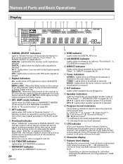
...LOUDNESS indicator Lights when loudness is on (refer to "Front Panel", 8, LOUDNESS on pages 26, 27). 0 DIRECT indicator Lights when direct playback is received in . ~ Speaker indicators Light to indicate the current speaker system (refer to "Front Panel", 7, SPEAKERS (A/B) on page 25) is used to...lights during actual playback of input signal selected for the current component (refer to "Front Panel", @, SIGNAL SELECT on , this indicator lights to receive FM broadcasts in all parts of a Dolby Digital signal. TUNED : Lights when a broadcast is selected. ! MONO : Lights when the tuner ...
...LOUDNESS indicator Lights when loudness is on (refer to "Front Panel", 8, LOUDNESS on pages 26, 27). 0 DIRECT indicator Lights when direct playback is received in . ~ Speaker indicators Light to indicate the current speaker system (refer to "Front Panel", 7, SPEAKERS (A/B) on page 25) is used to...lights during actual playback of input signal selected for the current component (refer to "Front Panel", @, SIGNAL SELECT on , this indicator lights to receive FM broadcasts in all parts of a Dolby Digital signal. TUNED : Lights when a broadcast is selected. ! MONO : Lights when the tuner ...
Operating Instructions
Page 25
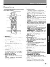
...input the station frequency during preset tuning. "MUTING" appears in standby. 2 MUTING button Press to operate the receiver. 0 1 2 3 4 5 6 7 8 9 RECEIVER TV MUTING FQ TV FUNC + ENTER - MIDNIGHT : Press to hear surround sound effectively at low volumes (...listening to a surround mode (refer to "Display", 5, Overload indicator on the remote operation mode. • [RECEIVER operations (press RECEIVER first)] : Press repeatedly to select the standard Dolby/ DTS mode and the ADVANCED THEATER modes. (Refer to...level of the input signals and prevent distortion (refer to page 21).
...input the station frequency during preset tuning. "MUTING" appears in standby. 2 MUTING button Press to operate the receiver. 0 1 2 3 4 5 6 7 8 9 RECEIVER TV MUTING FQ TV FUNC + ENTER - MIDNIGHT : Press to hear surround sound effectively at low volumes (...listening to a surround mode (refer to "Display", 5, Overload indicator on the remote operation mode. • [RECEIVER operations (press RECEIVER first)] : Press repeatedly to select the standard Dolby/ DTS mode and the ADVANCED THEATER modes. (Refer to...level of the input signals and prevent distortion (refer to page 21).
Operating Instructions
Page 26
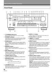
... adjust high frequencies in the range of Parts and Basic Operations Front Panel 1 2 3 4 56 7 8 9 0 AUDIO/VIDEO MULTI-CHANNEL RECEIVER STANDBY STANDBY/ON MPX CLASS MEMORY MODE STATION TUNING SELECT FREQUENCY / DTS DSP MODE Cinema Re - DIGITAL : Selects the digital audio signals. BASS... Press to switch between STATION and FREQUENCY. 7 SPEAKERS button Press repeatedly to adjust low frequencies in standby mode. (Please note that this receiver consumes a small amount of power (2.5 W) during the standby mode.) 3 CLASS button Press repeatedly to switch the preset station classes. ...
... adjust high frequencies in the range of Parts and Basic Operations Front Panel 1 2 3 4 56 7 8 9 0 AUDIO/VIDEO MULTI-CHANNEL RECEIVER STANDBY STANDBY/ON MPX CLASS MEMORY MODE STATION TUNING SELECT FREQUENCY / DTS DSP MODE Cinema Re - DIGITAL : Selects the digital audio signals. BASS... Press to switch between STATION and FREQUENCY. 7 SPEAKERS button Press repeatedly to adjust low frequencies in standby mode. (Please note that this receiver consumes a small amount of power (2.5 W) during the standby mode.) 3 CLASS button Press repeatedly to switch the preset station classes. ...
Operating Instructions
Page 27
... MODE button Press repeatedly to select a DSP sound mode (HALL 1, HALL 2, JAZZ, DANCE, THEATER 1, or THEATER 2). Use these , set SIGNAL SELECT to "ANALOG". • This receiver can only play back Dolby Digital, PCM (32kHz, 44kHz, and 48kHz), and DTS digital signal formats. SET UP • SIGNAL SELECT is fixed in digital...
... MODE button Press repeatedly to select a DSP sound mode (HALL 1, HALL 2, JAZZ, DANCE, THEATER 1, or THEATER 2). Use these , set SIGNAL SELECT to "ANALOG". • This receiver can only play back Dolby Digital, PCM (32kHz, 44kHz, and 48kHz), and DTS digital signal formats. SET UP • SIGNAL SELECT is fixed in digital...

Operating Instructions
Page 28
... with reverberation effects create a dynamic and beautiful sound characteristic of an orchestra performing in a concert hall, making it suitable for classical music. Sound Modes This receiver incorporates two surround modes for music or musical sources marked ( DOLBY ) or .R DIGITAL AC-3 D I G I T A L 5-D THEATER Simulates the clear and dynamic five channel sound of Dolby...
... with reverberation effects create a dynamic and beautiful sound characteristic of an orchestra performing in a concert hall, making it suitable for classical music. Sound Modes This receiver incorporates two surround modes for music or musical sources marked ( DOLBY ) or .R DIGITAL AC-3 D I G I T A L 5-D THEATER Simulates the clear and dynamic five channel sound of Dolby...
Operating Instructions
Page 29
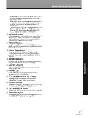
...source component. Each press switches between ANALOG and DIGITAL signal selection. To prevent noise, you need to make digital connections (Refer to pages 20, 21) and set in the digital input setting (Refer to an analog or digital input signal by playing back the DTS directly (no decoding). memo ... DIGITAL SP A SIG.SELECT 2 While SIGNAL SELECT is set to one of the component set SIGNAL SELECT to "ANALOG". • This receiver can be switched to page 20, 21) can only play back Dolby Digital, PCM (32kHz, 44kHz, and 48kHz), DTS digital signal formats. For more details, refer to the...
...source component. Each press switches between ANALOG and DIGITAL signal selection. To prevent noise, you need to make digital connections (Refer to pages 20, 21) and set in the digital input setting (Refer to an analog or digital input signal by playing back the DTS directly (no decoding). memo ... DIGITAL SP A SIG.SELECT 2 While SIGNAL SELECT is set to one of the component set SIGNAL SELECT to "ANALOG". • This receiver can be switched to page 20, 21) can only play back Dolby Digital, PCM (32kHz, 44kHz, and 48kHz), DTS digital signal formats. For more details, refer to the...
Operating Instructions
Page 30
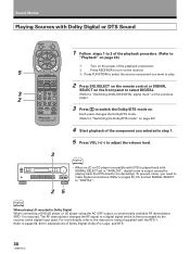
FQ 5 VOL VOL CHANNEL 1 Turn on the power of the playback component. 2 Press RECEIVER to turn on . To prevent noise, you need to make digital connections (Refer to pages 20, 21) and set in Dolby Digital When connecting a DVD/LD player or LD player using the AC-3 RF output, a commercially ...on the previous page.) CLASS TV/VCR FUNCTION DIRECT FL DIMMER MODE CHECK COMMANDER SET UP 3 Press to switch the Dolby/DTS mode on the receiver. 3 Press FUNCTION to select the source component you want to play. The RF demodulator changes the RF signal to a digital signal which is ...
FQ 5 VOL VOL CHANNEL 1 Turn on the power of the playback component. 2 Press RECEIVER to turn on . To prevent noise, you need to make digital connections (Refer to pages 20, 21) and set in Dolby Digital When connecting a DVD/LD player or LD player using the AC-3 RF output, a commercially ...on the previous page.) CLASS TV/VCR FUNCTION DIRECT FL DIMMER MODE CHECK COMMANDER SET UP 3 Press to switch the Dolby/DTS mode on the receiver. 3 Press FUNCTION to select the source component you want to play. The RF demodulator changes the RF signal to a digital signal which is ...


