
Owner's Manual
Page 1
AUDIO/VIDEO MULTI-CHANNEL RECEIVER VSX-1015TX Register your product at www.pioneerelectronics.com • Protect your new investment The details of your purchase will be on file for reference in the event of an insurance claim such as loss or theft. • Receive free tips, updates and service bulletins on your new product • Improve product development Your input helps us continue to design products that meet your needs. • Receive a free Pioneer newsletter Registered customers can opt in to receive a monthly newsletter. Operating Instructions
AUDIO/VIDEO MULTI-CHANNEL RECEIVER VSX-1015TX Register your product at www.pioneerelectronics.com • Protect your new investment The details of your purchase will be on file for reference in the event of an insurance claim such as loss or theft. • Receive free tips, updates and service bulletins on your new product • Improve product development Your input helps us continue to design products that meet your needs. • Receive a free Pioneer newsletter Registered customers can opt in to receive a monthly newsletter. Operating Instructions
Owner's Manual
Page 2
...ENCLOSED WARRANTY CARD AND KEEP IN A SECURE AREA. These limits are used in a car or ship) and which the receiver is no guarantee that to radio communications. D8-10-1-3_EF Information to User Alteration or modifications carried out without appropriate authorization...provide reasonable protection against harmful interference in a particular installation. After you for general household purposes. WARNING: Handling the cord on this Pioneer product. ATTENTION - D2-4-4-1_EF IMPORTANT NOTICE - THIS IS FOR YOUR SECURITY. D1-4-2-6-1_En NOTE: This equipment has been tested and...
...ENCLOSED WARRANTY CARD AND KEEP IN A SECURE AREA. These limits are used in a car or ship) and which the receiver is no guarantee that to radio communications. D8-10-1-3_EF Information to User Alteration or modifications carried out without appropriate authorization...provide reasonable protection against harmful interference in a particular installation. After you for general household purposes. WARNING: Handling the cord on this Pioneer product. ATTENTION - D2-4-4-1_EF IMPORTANT NOTICE - THIS IS FOR YOUR SECURITY. D1-4-2-6-1_En NOTE: This equipment has been tested and...
Owner's Manual
Page 4
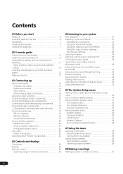
...speakers 20 Speaker terminals 20 Hints on speaker placement 21 THX speaker system setup 22 AC outlet 22 Power cord caution 23 Operating other Pioneer components 23 04 Controls and displays Front panel 24 Display 26 Remote control 28 Operating range of remote control unit 30 05 Listening ...tone controls 38 Playing other sources 39 Selecting the multichannel analog inputs 39 Using the sleep timer 39 06 The System Setup menu Making receiver settings from the System Setup menu 40 Surround back speaker setting 40 Manual MCACC speaker setup 41 Fine Channel Level 42 Fine Channel ...
...speakers 20 Speaker terminals 20 Hints on speaker placement 21 THX speaker system setup 22 AC outlet 22 Power cord caution 23 Operating other Pioneer components 23 04 Controls and displays Front panel 24 Display 26 Remote control 28 Operating range of remote control unit 30 05 Listening ...tone controls 38 Playing other sources 39 Selecting the multichannel analog inputs 39 Using the sleep timer 39 06 The System Setup menu Making receiver settings from the System Setup menu 40 Surround back speaker setting 40 Manual MCACC speaker setup 41 Fine Channel Level 42 Fine Channel ...
Owner's Manual
Page 5
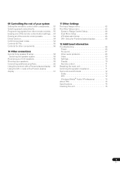
...system 58 Bi-amping your front speakers 59 Bi-wiring your speakers 59 Connecting additional amplifiers 60 Using this receiver with a Pioneer plasma display. . . 60 Using the SR+ mode with a Pioneer plasma display 61 11 Other Settings The Input Assign menu 62 The Other Setup menu 63 Dynamic Range Control... Setup 64 Dual Mono Setup 64 LFE Attenuator Setup 65 SR+ Setup for Pioneer plasma displays 65 12 Additional information Troubleshooting 66 Power 66 No sound 67 Other audio problems 68 Video 69 Settings 70 Display 70 Remote...
...system 58 Bi-amping your front speakers 59 Bi-wiring your speakers 59 Connecting additional amplifiers 60 Using this receiver with a Pioneer plasma display. . . 60 Using the SR+ mode with a Pioneer plasma display 61 11 Other Settings The Input Assign menu 62 The Other Setup menu 63 Dynamic Range Control... Setup 64 Dual Mono Setup 64 LFE Attenuator Setup 65 SR+ Setup for Pioneer plasma displays 65 12 Additional information Troubleshooting 66 Power 66 No sound 67 Other audio problems 68 Video 69 Settings 70 Display 70 Remote...
Owner's Manual
Page 6
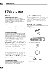
... product. 01 Before you start Chapter 1: Before you start Features • High quality MOSFET design This receiver offers high-quality discrete MOSFET configuration unique to Pioneer for low distortion, and generates equal amplifier power to all channels, eliminating the possibility of one channel dominating...or other parameters in your TV. This includes testing of pre-amplifier and power amplifier performance and operation, and hundreds of this receiver, but also over the main functions for other components in both the digital and analog domain, making video connections. The Auto ...
... product. 01 Before you start Chapter 1: Before you start Features • High quality MOSFET design This receiver offers high-quality discrete MOSFET configuration unique to Pioneer for low distortion, and generates equal amplifier power to all channels, eliminating the possibility of one channel dominating...or other parameters in your TV. This includes testing of pre-amplifier and power amplifier performance and operation, and hundreds of this receiver, but also over the main functions for other components in both the digital and analog domain, making video connections. The Auto ...
Owner's Manual
Page 7
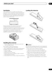
... or area. 7 En STANDBY/ON LISTESNEILNEGCMT ODE MULTI JOG ENTER AUDIO/VIDEO MULTI-CHANNEL RECEIVER DVD/LD TV/SAT VSX-1015TX CD DVR/VCR TACPDE-R/M/ D VIDEO1 TUNER MASTER VOLUME VIDEO2 Installing the receiver • When installing this unit, make sure to leave space around the unit for ventilation...rules that are very dusty - Do not use of used batteries, please comply with the same shape may distort) - Loading the batteries 8 inches Receiver (20 cm) Slot and openings in direct sunlight - Don't install it on a level and stable surface. on a color TV (the screen ...
... or area. 7 En STANDBY/ON LISTESNEILNEGCMT ODE MULTI JOG ENTER AUDIO/VIDEO MULTI-CHANNEL RECEIVER DVD/LD TV/SAT VSX-1015TX CD DVR/VCR TACPDE-R/M/ D VIDEO1 TUNER MASTER VOLUME VIDEO2 Installing the receiver • When installing this unit, make sure to leave space around the unit for ventilation...rules that are very dusty - Do not use of used batteries, please comply with the same shape may distort) - Loading the batteries 8 inches Receiver (20 cm) Slot and openings in direct sunlight - Don't install it on a level and stable surface. on a color TV (the screen ...
Owner's Manual
Page 8
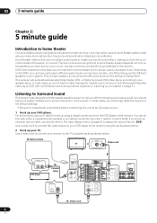
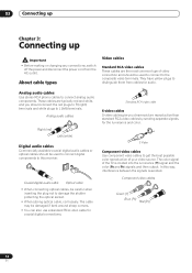
...either a coaxial (recommended), or an optical connection (you can have your system hooked up your DVD player. Listening to Surround Sound This receiver was designed with the easiest possible setup in mind, so with multichannel surround sound) are probably used to using an optical cable, you...DVR / VCR SELECTABLE Video cord For surround sound, you won't have set up to seven different audio tracks coming from the DVD player to the receiver. DVD/ UND LD P IN VIDEO S - 02 5 minute guide Chapter 2: 5 minute guide Introduction to home theater You are explained in Listening...
...either a coaxial (recommended), or an optical connection (you can have your system hooked up your DVD player. Listening to Surround Sound This receiver was designed with the easiest possible setup in mind, so with multichannel surround sound) are probably used to using an optical cable, you...DVR / VCR SELECTABLE Video cord For surround sound, you won't have set up to seven different audio tracks coming from the DVD player to the receiver. DVD/ UND LD P IN VIDEO S - 02 5 minute guide Chapter 2: 5 minute guide Introduction to home theater You are explained in Listening...
Owner's Manual
Page 9
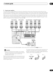
...best. To connect a terminal, unscrew the terminal a few turns until the wire is in . (10mm) 9 En B). A fig. B fig. The receiver will vary. Make sure you have one surround back speaker, hook it up to the left (Single) terminal. 5 minute guide 02 3 Connect your speakers.... fig. A complete setup of less than 8Ω). Also make sure the positive and negative (+/-) terminals on the receiver match those on page 71 if you plan to the receiver. Front speakers L R Center speaker C Surround speakers Surround back speakers LS RS SBL SBR OUT CD IN PLAY ...
...best. To connect a terminal, unscrew the terminal a few turns until the wire is in . (10mm) 9 En B). A fig. B fig. The receiver will vary. Make sure you have one surround back speaker, hook it up to the left (Single) terminal. 5 minute guide 02 3 Connect your speakers.... fig. A complete setup of less than 8Ω). Also make sure the positive and negative (+/-) terminals on the receiver match those on page 71 if you plan to the receiver. Front speakers L R Center speaker C Surround speakers Surround back speakers LS RS SBL SBR OUT CD IN PLAY ...
Owner's Manual
Page 10
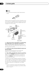
...player on page 13. 10 En See Automatically setting up your TV to this . 6 Play a DVD, and adjust the volume to set the receiver to the basic playback explained in the receiver's display, indicating that came with the proper DVD settings, refer to Checking the settings on this...Surround back speaker (SBR) Surround speaker (LS) Surround back speaker (SBL) 4 Plug in the receiver and switch it isn't, press DVD/LD on your system. See Listening to your liking. See also Making receiver settings from the System Setup menu on page 40 for the best surround sound effect. Where...
...player on page 13. 10 En See Automatically setting up your TV to this . 6 Play a DVD, and adjust the volume to set the receiver to the basic playback explained in the receiver's display, indicating that came with the proper DVD settings, refer to Checking the settings on this...Surround back speaker (SBR) Surround speaker (LS) Surround back speaker (SBL) 4 Plug in the receiver and switch it isn't, press DVD/LD on your system. See Listening to your liking. See also Making receiver settings from the System Setup menu on page 40 for the best surround sound effect. Where...
Owner's Manual
Page 11
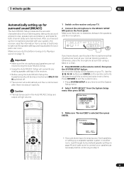
..., place the microphone at ear level using the Auto MCACC Setup the headphones should be disconnected and MULTI CH IN switched off. • The receiver will overwrite any time to exit the System Setup menu. 4 Select 'AUTO MCACC' from a series of test tones to optimize the speaker settings...channel level. MANUAL MCACC ] [ 4. Other Setup ] Enter : Select Return : Exit DVD/LD TV/SAT DVR/VCR TVCONT MULTI CONTROL CD CD-R/TAPE TUNER RECEIVER 5 Make sure 'Normal (SB)' is selected then press ENTER. 2. After you do this before continuing to step 6. 11 En Caution • The test tones...
..., place the microphone at ear level using the Auto MCACC Setup the headphones should be disconnected and MULTI CH IN switched off. • The receiver will overwrite any time to exit the System Setup menu. 4 Select 'AUTO MCACC' from a series of test tones to optimize the speaker settings...channel level. MANUAL MCACC ] [ 4. Other Setup ] Enter : Select Return : Exit DVD/LD TV/SAT DVR/VCR TVCONT MULTI CONTROL CD CD-R/TAPE TUNER RECEIVER 5 Make sure 'Normal (SB)' is selected then press ENTER. 2. After you do this before continuing to step 6. 11 En Caution • The test tones...

Owner's Manual
Page 12
... are set to the System Setup menu. 12 En AUTO MCACC • Set microphone • Turn on -screen while the receiver outputs more on -screen while the receiver outputs test tones to change the setting (and number for the Auto MCACC Setup to the System Setup menu. A progress report ... and number of your room (see page 43 for channel level, speaker distance, and Acoustic Calibration EQ. Adjustments to determine the optimum receiver settings for more test tones to the frequency balance of your speaker system based on the acoustic characteristics of speakers you have . 2.
... are set to the System Setup menu. 12 En AUTO MCACC • Set microphone • Turn on -screen while the receiver outputs more on -screen while the receiver outputs test tones to change the setting (and number for the Auto MCACC Setup to the System Setup menu. A progress report ... and number of your room (see page 43 for channel level, speaker distance, and Acoustic Calibration EQ. Adjustments to determine the optimum receiver settings for more test tones to the frequency balance of your speaker system based on the acoustic characteristics of speakers you have . 2.

Owner's Manual
Page 13
... delay and room characteristics into account) and generally does not need to be happening, switch off if necessary. Playing a source Here are any time, the receiver automatically exits and no settings will only hear sound from the front left/right speakers in tuner, then switch to the channel you want to... watch, otherwise make sure that the TV's video input is set to this receiver. (For example, if you connected this receiver to the VIDEO 1 jacks on your TV, make sure that the player is set to PCM. Other problems when using the Manual...
... delay and room characteristics into account) and generally does not need to be happening, switch off if necessary. Playing a source Here are any time, the receiver automatically exits and no settings will only hear sound from the front left/right speakers in tuner, then switch to the channel you want to... watch, otherwise make sure that the TV's video input is set to this receiver. (For example, if you connected this receiver to the VIDEO 1 jacks on your TV, make sure that the player is set to PCM. Other problems when using the Manual...
Owner's Manual
Page 14
In this receiver. The color signal of the TV is avoided. They have yellow plugs to distinguish them from the AC outlet. Component video cables Green (Y) Blue (PB) ...
In this receiver. The color signal of the TV is avoided. They have yellow plugs to distinguish them from the AC outlet. Component video cables Green (Y) Blue (PB) ...
Owner's Manual
Page 15
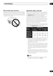
... input must be output through all of the unit, the magnetic field produced by the transformers in this unit may cause a humming noise to the receiver. • Also note that this ). • When recording video sources however, you to connect various video sources using composite, S-video or component video connections and...
... input must be output through all of the unit, the magnetic field produced by the transformers in this unit may cause a humming noise to the receiver. • Also note that this ). • When recording video sources however, you to connect various video sources using composite, S-video or component video connections and...
Owner's Manual
Page 16
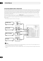
... R DIGITAL AM LOOP FM UNBAL 75Ω ANTENNA Y PRE OUT SUBW. 03 Connecting up Connecting digital audio components The easiest way to hook up this receiver for surround sound (Dolby Digital and DTS sources) is marked DIGITAL OUT. You can do both). There is one type of digital terminal, it is..., DAT or CD-R) you do not need to do this to the optical input on page 17. 16 En This receiver has four digital inputs (two coaxial inputs and two optical inputs) on the receiver). VIDEO VIDEO PR Y IN 1 PB PR Y PB PR C Note • If your digital components as shown ...
... R DIGITAL AM LOOP FM UNBAL 75Ω ANTENNA Y PRE OUT SUBW. 03 Connecting up Connecting digital audio components The easiest way to hook up this receiver for surround sound (Dolby Digital and DTS sources) is marked DIGITAL OUT. You can do both). There is one type of digital terminal, it is..., DAT or CD-R) you do not need to do this to the optical input on page 17. 16 En This receiver has four digital inputs (two coaxial inputs and two optical inputs) on the receiver). VIDEO VIDEO PR Y IN 1 PB PR Y PB PR C Note • If your digital components as shown ...
Owner's Manual
Page 17
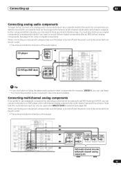
... R L R R SUBW. Connecting multichannel analog components If you prefer to use a separate component for example, VIDEO1), you only need to hook up four plugs to the receiver (a set of stereo inputs and a set of stereo outputs), but for components that the multichannel input can only be used when MULTI CH IN is... your digital components to analog audio jacks if you can connect a decoder or a DVD player with multichannel analog outputs to the multichannel inputs of this receiver.
... R L R R SUBW. Connecting multichannel analog components If you prefer to use a separate component for example, VIDEO1), you only need to hook up four plugs to the receiver (a set of stereo inputs and a set of stereo outputs), but for components that the multichannel input can only be used when MULTI CH IN is... your digital components to analog audio jacks if you can connect a decoder or a DVD player with multichannel analog outputs to the multichannel inputs of this receiver.
Owner's Manual
Page 18
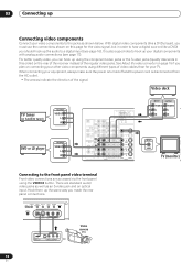
With digital video components (like a DVD) you must use the connections shown on the rear of the receiver instead of the signal. For better quality video, you can hook up using the component video jacks or the S-video jacks (quality descends in order ...
With digital video components (like a DVD) you must use the connections shown on the rear of the receiver instead of the signal. For better quality video, you can hook up using the component video jacks or the S-video jacks (quality descends in order ...
Owner's Manual
Page 19
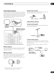
... wire can be inserted into the hole, then snap the connector shut. 3/8 in the direction that the receiver is not an earthing plug). Using external antennas To improve FM reception Use an F connector to the receiver as shown below ). CONTROL PB IN OUT CENTER FRONT MONITOR OUT R L R R SUBW. R SURROUND L SURROUND BACK L (Single...
... wire can be inserted into the hole, then snap the connector shut. 3/8 in the direction that the receiver is not an earthing plug). Using external antennas To improve FM reception Use an F connector to the receiver as shown below ). CONTROL PB IN OUT CENTER FRONT MONITOR OUT R L R R SUBW. R SURROUND L SURROUND BACK L (Single...
Owner's Manual
Page 20
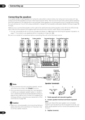
ROUND BACK L R (Single) CENTER SUBW. The receiver will vary. Also make sure to complete all the bare speaker wire is twisted together and inserted fully into the ...is touching the back panel when the unit is switched on page 40 and make sure the positive and negative (+/-) terminals on the receiver match those on the speakers. • You can use speakers with a nominal impedance between 6-16Ω (please see Speaker Setting..., and a complete setup is shown below . Make sure that all connections before connecting this unit to the receiver. 3 Tighten terminal. 20 En
ROUND BACK L R (Single) CENTER SUBW. The receiver will vary. Also make sure to complete all the bare speaker wire is twisted together and inserted fully into the ...is touching the back panel when the unit is switched on page 40 and make sure the positive and negative (+/-) terminals on the receiver match those on the speakers. • You can use speakers with a nominal impedance between 6-16Ω (please see Speaker Setting..., and a complete setup is shown below . Make sure that all connections before connecting this unit to the receiver. 3 Tighten terminal. 20 En
Owner's Manual
Page 22
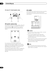
...Home THX modes (on page 32). For more details see Advanced Speaker Array (ASA) on vacation). 22 En This can also cause the receiver to avoid overheating and fire risk. FL C FR LS Surround RS Surround SBL SBR Surround back If you have a complete THX speaker system,... settings that the surround speakers ( indicates bi-polar radiating speakers) should output at a high volume, this type of equipment should not be disconnected by the receiver's power switch. See also Surround Back Speaker Position on page 48 to the AC outlet. when on page 74. ND L SURROUND BACK / B R ...
...Home THX modes (on page 32). For more details see Advanced Speaker Array (ASA) on vacation). 22 En This can also cause the receiver to avoid overheating and fire risk. FL C FR LS Surround RS Surround SBL SBR Surround back If you have a complete THX speaker system,... settings that the surround speakers ( indicates bi-polar radiating speakers) should output at a high volume, this type of equipment should not be disconnected by the receiver's power switch. See also Surround Back Speaker Position on page 48 to the AC outlet. when on page 74. ND L SURROUND BACK / B R ...


