
Owner's Manual
Page 3
... cabinet. ENGLISH SAFETY PRECAUTIONS IMPORTANT SAFETY INSTRUCTIONS READ INSTRUCTIONS - This product should be located in the vicinity of overhead power lines or other controls may touch dangerous voltage points or shortout parts that produce heat. If you are provided for ...OUTDOOR ANTENNA GROUNDING - LIGHTNING - Quick stops, excessive force, and uneven surfaces may fall into the outlet, try reversing the plug. POWER SOURCES - ACCESSORIES - Never push objects of any way. ÷ When the product exhibits a distinct change in installation such as ...
... cabinet. ENGLISH SAFETY PRECAUTIONS IMPORTANT SAFETY INSTRUCTIONS READ INSTRUCTIONS - This product should be located in the vicinity of overhead power lines or other controls may touch dangerous voltage points or shortout parts that produce heat. If you are provided for ...OUTDOOR ANTENNA GROUNDING - LIGHTNING - Quick stops, excessive force, and uneven surfaces may fall into the outlet, try reversing the plug. POWER SOURCES - ACCESSORIES - Never push objects of any way. ÷ When the product exhibits a distinct change in installation such as ...

Owner's Manual
Page 5
...9675; ○ ○ ○ ○ ○ ○ ○ ○ ○ ○ ○ ○ ○ ○ FEATURES ÷ Incorporation of the power consumption in standby mode is 0.6 W. ○ ○ ○ ○ ○ ○ ○ ○ ○ ○ ○ ○ ○ ○ ...producing a 50 inch wide screen, which is in the case of definition, using originally developed PIONEER technology for PDP-505HD table top placement. (For details, please consult the dealer where this unit was purchased.) ...
...9675; ○ ○ ○ ○ ○ ○ ○ ○ ○ ○ ○ ○ ○ ○ FEATURES ÷ Incorporation of the power consumption in standby mode is 0.6 W. ○ ○ ○ ○ ○ ○ ○ ○ ○ ○ ○ ○ ○ ○ ...producing a 50 inch wide screen, which is in the case of definition, using originally developed PIONEER technology for PDP-505HD table top placement. (For details, please consult the dealer where this unit was purchased.) ...
Owner's Manual
Page 6
... 10 Connection to INPUT2 10 Connection to INPUT3 and INPUT4 11 About DTV Set Top Box connection 14 Control cord connection 15 Power cord connection 15 How to route cables 16 SETTING UP THE SYSTEM 17 Setup after connection 17 OPERATIONS 20 Selecting an input ...source 20 Screen size selection 22 POWER SAVE 26 Labeling the Inputs 27 ○ ○ ○ ○ ○ ○ ○ ○ ○ ○ ○ ○ ○ ○ ○ ○...
... 10 Connection to INPUT2 10 Connection to INPUT3 and INPUT4 11 About DTV Set Top Box connection 14 Control cord connection 15 Power cord connection 15 How to route cables 16 SETTING UP THE SYSTEM 17 Setup after connection 17 OPERATIONS 20 Selecting an input ...source 20 Screen size selection 22 POWER SAVE 26 Labeling the Inputs 27 ○ ○ ○ ○ ○ ○ ○ ○ ○ ○ ○ ○ ○ ○ ○ ○...
Owner's Manual
Page 7
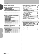
... all the necessary points regarding installation of the plasma display and connections to a wide variety of the picture. 1,6 2,3,5 CH VOL MUTING RECEIVER EDIT/ LEARN SOURCE POWER DVD TOP MENU MENU 1 8 TV/SAT/DTV/DVD MENU % SAT/DTV GUIDE SET/ SELECT % FAVORITES 7 3 VCR REC ¶ 4 (SAT)/DTV INFO ¡ ¢ 2,3,4 CU-PDP008...
... all the necessary points regarding installation of the plasma display and connections to a wide variety of the picture. 1,6 2,3,5 CH VOL MUTING RECEIVER EDIT/ LEARN SOURCE POWER DVD TOP MENU MENU 1 8 TV/SAT/DTV/DVD MENU % SAT/DTV GUIDE SET/ SELECT % FAVORITES 7 3 VCR REC ¶ 4 (SAT)/DTV INFO ¡ ¢ 2,3,4 CU-PDP008...
Owner's Manual
Page 9
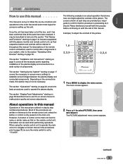
...9675;or○ie○s○ ○ ○ ○ ○ ○ ○ Check that the following accessories were supplied. 1 Power cord ○ ○ ○ ○ 6 Bead band x 2 ○ ○ ○ ○ ○ ○ ...○ ○ ○ 2 Remote control unit 7 4 1 2 MODESCREEN STA/IVNNCTDPRVUBTY/S/COABTNL DTV/LDDVD 3 POWER AUTO 4 AUDIO INPUT CC STILL RECEIVER DISPLAY 1 5 2 3 CLEAR MOVDIEEW DTV ¶ 8 6 0 9 CH RETUCRHN 8 POWSEORULRECAEREDNIT/ % % MTEONPUDMVENDU 1 SELSEECTT/ %...
...9675;or○ie○s○ ○ ○ ○ ○ ○ ○ Check that the following accessories were supplied. 1 Power cord ○ ○ ○ ○ 6 Bead band x 2 ○ ○ ○ ○ ○ ○ ...○ ○ ○ 2 Remote control unit 7 4 1 2 MODESCREEN STA/IVNNCTDPRVUBTY/S/COABTNL DTV/LDDVD 3 POWER AUTO 4 AUDIO INPUT CC STILL RECEIVER DISPLAY 1 5 2 3 CLEAR MOVDIEEW DTV ¶ 8 6 0 9 CH RETUCRHN 8 POWSEORULRECAEREDNIT/ % % MTEONPUDMVENDU 1 SELSEECTT/ %...
Owner's Manual
Page 10
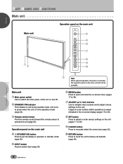
... been connected, ○ ○ the operation panel on the main unit will not be ○ operable. ○ ○ ○ Main unit 1 Main power switch Use to switch the main power of cursor buttons within operations is in the operation mode (page 20). 3 Remote control sensor Point the remote control toward the remote...
... been connected, ○ ○ the operation panel on the main unit will not be ○ operable. ○ ○ ○ Main unit 1 Main power switch Use to switch the main power of cursor buttons within operations is in the operation mode (page 20). 3 Remote control sensor Point the remote control toward the remote...
Owner's Manual
Page 11
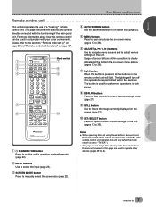
... "Remote control unit functions" on page 42". 1 2 3 4 5 6 TV CBL DTVDVD /VCR /SAT /LD STANDBY/ON INPUT 1 23 SCREEN MODE AUTO STILL 4 DISPLAY POWER AUDIO INPUT RECEIVER CC CLEAR DTV VIEW MODE 123 456 789 ¶ 0 CH ENTER CH RETURN CH VOL MUTING RECEIVER EDIT/ LEARN SOURCE... POWER DVD TOP MENU MENU 1 8 % % TV/SAT/DTV/DVD MENU % SAT/DTV GUIDE SET/ SELECT % FAVORITES 7 3 VCR REC ¶ 4 (SAT) /DTV INFO ¡ ¢ Mode switch 7 8...
... "Remote control unit functions" on page 42". 1 2 3 4 5 6 TV CBL DTVDVD /VCR /SAT /LD STANDBY/ON INPUT 1 23 SCREEN MODE AUTO STILL 4 DISPLAY POWER AUDIO INPUT RECEIVER CC CLEAR DTV VIEW MODE 123 456 789 ¶ 0 CH ENTER CH RETURN CH VOL MUTING RECEIVER EDIT/ LEARN SOURCE... POWER DVD TOP MENU MENU 1 8 % % TV/SAT/DTV/DVD MENU % SAT/DTV GUIDE SET/ SELECT % FAVORITES 7 3 VCR REC ¶ 4 (SAT) /DTV INFO ¡ ¢ Mode switch 7 8...
Owner's Manual
Page 12
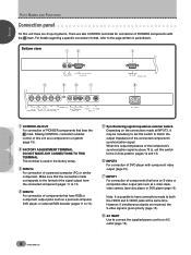
.../PR C-VIDEO INPUT2 VIDEO S-VIDEO INPUT1 ○ ○ AC INLET ○ ○ ○ ○ ○ 1 CONTROL IN/OUT For connection of PIONEER components with component video output (page 10). 7 INPUT1 For connection of components that have an S-video or composite video output jack such as a video deck...refer to match the output impedance of the component's synchronization signal is given priority (page 10). 8 AC INLET Use to connect the supplied power cord to both the VIDEO and S-VIDEO jacks at INPUT3, it may be necessary to set this switch to the 2.2 kΩ position...
.../PR C-VIDEO INPUT2 VIDEO S-VIDEO INPUT1 ○ ○ AC INLET ○ ○ ○ ○ ○ 1 CONTROL IN/OUT For connection of PIONEER components with component video output (page 10). 7 INPUT1 For connection of components that have an S-video or composite video output jack such as a video deck...refer to match the output impedance of the component's synchronization signal is given priority (page 10). 8 AC INLET Use to connect the supplied power cord to both the VIDEO and S-VIDEO jacks at INPUT3, it may be necessary to set this switch to the 2.2 kΩ position...
Owner's Manual
Page 17
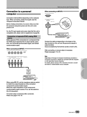
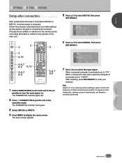
...separate SYNC connections for a component that this switch to the 2.2 kΩ position. Secure by tightening the terminal screws on this unit's main power is necessary after connection. After connecting, on-screen setup is above 75 Ω, set the impedance selector switch to match the output impedance ... using INPUT3, set this unit is compatible with the computer or sold separately may be sure to make sure that the personal computer's power and this unit and the personal computer's output terminal. ENGLISH IN○ST○A○LL○AT○IO○N○A○...
...separate SYNC connections for a component that this switch to the 2.2 kΩ position. Secure by tightening the terminal screws on this unit's main power is necessary after connection. After connecting, on-screen setup is above 75 Ω, set the impedance selector switch to match the output impedance ... using INPUT3, set this unit is compatible with the computer or sold separately may be sure to make sure that the personal computer's power and this unit and the personal computer's output terminal. ENGLISH IN○ST○A○LL○AT○IO○N○A○...

Owner's Manual
Page 19
...complete all component connections have been completed. 1 2 1 Connect the power cord to control. Always be sure to connect the power cord to the CONTROL IN jack on another unit, the remote sensor of connected PIONEER components that component will no resistance). ○ ○ INSTALLATION AND...efficiency protection. Point the remote control unit of the connected component at the remote control sensor on this unit to this unit. 2 Plug the power cord into a power outlet. ○ ○ ○ ○ IN OUT CONTROL CONTROL IN OUT CONTROL IN OUT ○ ○ ○ &#...
...complete all component connections have been completed. 1 2 1 Connect the power cord to control. Always be sure to connect the power cord to the CONTROL IN jack on another unit, the remote sensor of connected PIONEER components that component will no resistance). ○ ○ INSTALLATION AND...efficiency protection. Point the remote control unit of the connected component at the remote control sensor on this unit to this unit. 2 Plug the power cord into a power outlet. ○ ○ ○ ○ IN OUT CONTROL CONTROL IN OUT CONTROL IN OUT ○ ○ ○ &#...
Owner's Manual
Page 21
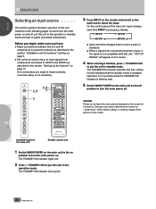
...MODE RETURN 2 2 3 4,10 5,6,7 8,9 4,10 5,6,7 8,9 TV CBL DTVDVD /VCR /SAT /LD STANDBY/ON INPUT 1 23 SCREEN MODE AUTO STILL 4 DISPLAY POWER AUDIO INPUT RECEIVER C C CLEAR DTV VIEW MODE 123 456 789 ¶ 0 CH ENTER CH RETURN CH VOL MUTING RECEIVER EDIT/ LEARN SOURCE... VCR REC ¶ 4 ¡ ¢ 3 5,6,7 8,9 CU-PDP008 Î PLASMA DISPLAY REMOTE CONTROL UNIT 1 Switch MAIN POWER on the main unit to the on position to turn the main power on. Note Steps 6 to 7 are necessary when inputting a signal of other than a personal computer is necessary. SETTING UP THE...
...MODE RETURN 2 2 3 4,10 5,6,7 8,9 4,10 5,6,7 8,9 TV CBL DTVDVD /VCR /SAT /LD STANDBY/ON INPUT 1 23 SCREEN MODE AUTO STILL 4 DISPLAY POWER AUDIO INPUT RECEIVER C C CLEAR DTV VIEW MODE 123 456 789 ¶ 0 CH ENTER CH RETURN CH VOL MUTING RECEIVER EDIT/ LEARN SOURCE... VCR REC ¶ 4 ¡ ¢ 3 5,6,7 8,9 CU-PDP008 Î PLASMA DISPLAY REMOTE CONTROL UNIT 1 Switch MAIN POWER on the main unit to the on position to turn the main power on. Note Steps 6 to 7 are necessary when inputting a signal of other than a personal computer is necessary. SETTING UP THE...
Owner's Manual
Page 23
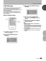
... SYNC : OF F I NPUT LABEL EX I NPUT LABEL EXI T USE: END: MENU ○ ○ Setup of G ON SYNC connection 1,5 CH VOL MUTING RECEIVER EDIT/ LEARN SOURCE POWER DVD TOP MENU MENU 1 8 % % TV/SAT/DTV/DVD MENU % SAT/DTV GUIDE SET/ SELECT % FAVORITES 7 3 VCR REC ¶ 4 (SAT)/DTV INFO ¡ ¢ 2,3,4 CU-PDP008...
... SYNC : OF F I NPUT LABEL EX I NPUT LABEL EXI T USE: END: MENU ○ ○ Setup of G ON SYNC connection 1,5 CH VOL MUTING RECEIVER EDIT/ LEARN SOURCE POWER DVD TOP MENU MENU 1 8 % % TV/SAT/DTV/DVD MENU % SAT/DTV GUIDE SET/ SELECT % FAVORITES 7 3 VCR REC ¶ 4 (SAT)/DTV INFO ¡ ¢ 2,3,4 CU-PDP008...
Owner's Manual
Page 24
...the on-screen menu to input signals from a personal computer is input, if the signal is finished, press STANDBY/ON to turn the main power off , put this unit, "OUT OF RANGE" will blink and then remain lit (red) indicating that the standby mode is not necessary...9675; ○ ○ ○ ○ ○ ○ ○ ○ ○ ○ ○ ○ ○ ○ ○ ○ ○ ○ ○ 5 Switch MAIN POWER on page 17. On the control panel of the main unit, input changes each time INPUT is pressed as "screen burn" which leaves a ghost, or...
...the on-screen menu to input signals from a personal computer is input, if the signal is finished, press STANDBY/ON to turn the main power off , put this unit, "OUT OF RANGE" will blink and then remain lit (red) indicating that the standby mode is not necessary...9675; ○ ○ ○ ○ ○ ○ ○ ○ ○ ○ ○ ○ ○ ○ ○ ○ ○ ○ ○ 5 Switch MAIN POWER on page 17. On the control panel of the main unit, input changes each time INPUT is pressed as "screen burn" which leaves a ghost, or...
Owner's Manual
Page 25
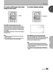
...; ○ ○ ○ ○ TV CBL DTVDVD /VCR /SAT /LD STANDBY/ON INPUT 1 23 SCREEN MODE AUTO STILL 4 DISPLAY POWER AUDIO INPUT RECEIVER C C CLEAR DTV VIEW MODE 123 456 STILL Press STILL on the remote control unit. ENGLISH OPERATIONS To create a still image of...; ○ ○ ○ ○ ○ ○ ○ ○ ○ TV CBL DTVDVD /VCR /SAT /LD STANDBY/ON INPUT 1 23 SCREEN MODE AUTO STILL 4 DISPLAY POWER AUDIO INPUT RECEIVER C C CLEAR DTV VIEW MODE 123 456 DISPLAY FH : FV : I NPUT 4 P C RGB 4 8 . 0 k HZ 6 0 . 0 HZ STD F UL L ...
...; ○ ○ ○ ○ TV CBL DTVDVD /VCR /SAT /LD STANDBY/ON INPUT 1 23 SCREEN MODE AUTO STILL 4 DISPLAY POWER AUDIO INPUT RECEIVER C C CLEAR DTV VIEW MODE 123 456 STILL Press STILL on the remote control unit. ENGLISH OPERATIONS To create a still image of...; ○ ○ ○ ○ ○ ○ ○ ○ ○ TV CBL DTVDVD /VCR /SAT /LD STANDBY/ON INPUT 1 23 SCREEN MODE AUTO STILL 4 DISPLAY POWER AUDIO INPUT RECEIVER C C CLEAR DTV VIEW MODE 123 456 DISPLAY FH : FV : I NPUT 4 P C RGB 4 8 . 0 k HZ 6 0 . 0 HZ STD F UL L ...
Owner's Manual
Page 26
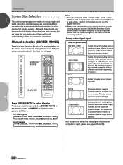
... its original screen frame size. (To prevent screen burn on this unit, the displayed position of the manufacturer's intentions. Provides a more expansive, powerful image. ○ ○ Press SCREEN MODE to display a non-wide screen 4:3 picture fully on .) Suitable for full display of various height...source that has subtitles. (For screen sizes when the video signal of the author protected under copyright law. Provides a more expansive, powerful image. Although these modes are viewing. This screen size is convenient when viewing a Cinemascope size image that you make use of ...
... its original screen frame size. (To prevent screen burn on this unit, the displayed position of the manufacturer's intentions. Provides a more expansive, powerful image. ○ ○ Press SCREEN MODE to display a non-wide screen 4:3 picture fully on .) Suitable for full display of various height...source that has subtitles. (For screen sizes when the video signal of the author protected under copyright law. Provides a more expansive, powerful image. Although these modes are viewing. This screen size is convenient when viewing a Cinemascope size image that you make use of ...

Owner's Manual
Page 27
... SCREEN, then press SET/SELECT. Using the remote control unit TV CBL DTVDVD /VCR /SAT /LD STANDBY/ON INPUT 1 23 SCREEN MODE AUTO STILL 4 DISPLAY POWER AUDIO INPUT RECEIVER CC CLEAR DTV VIEW MODE 123 456 AUTO SCREEN ○ ○ ○ ○ ○ ○ ○ ○ ○ ○ ○ ○ ○...
... SCREEN, then press SET/SELECT. Using the remote control unit TV CBL DTVDVD /VCR /SAT /LD STANDBY/ON INPUT 1 23 SCREEN MODE AUTO STILL 4 DISPLAY POWER AUDIO INPUT RECEIVER CC CLEAR DTV VIEW MODE 123 456 AUTO SCREEN ○ ○ ○ ○ ○ ○ ○ ○ ○ ○ ○ ○ ○...

Owner's Manual
Page 28
... CINEMA WIDE or ZOOM setting, the image may not be centered on -screen menu. ○ ○ 1,5 CH RETURN CH VOL MUTING RECEIVER EDIT/ LEARN SOURCE POWER DVD TOP MENU MENU 1 8 TV/SAT/DTV/DVD MENU % SAT/DTV GUIDE SET/ SELECT % FAVORITES 7 3 VCR REC ¶ 4 (SAT)/DTV INFO ¡ ¢ 2,3,4 ○ ○...
... CINEMA WIDE or ZOOM setting, the image may not be centered on -screen menu. ○ ○ 1,5 CH RETURN CH VOL MUTING RECEIVER EDIT/ LEARN SOURCE POWER DVD TOP MENU MENU 1 8 TV/SAT/DTV/DVD MENU % SAT/DTV GUIDE SET/ SELECT % FAVORITES 7 3 VCR REC ¶ 4 (SAT)/DTV INFO ¡ ¢ 2,3,4 ○ ○...
Owner's Manual
Page 30
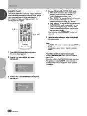
...○ ○ ○ ○ ○ ○ ○ ○ ○ ○ ○ ○ ○ Notes • The POWER SAVE setting is common to all inputs (INPUT1 to INPUT4). • When SIGNAL is input. To put the unit in operation mode. ENGLISH % % OPERATIONS P&#...Press 5/∞ to "VIDEO", "MODE2" cannot be put the unit in operation mode again. ○ ○ ○ ○ ○ 3 Press 5/∞ to select POWER SAVE, then press SET/SELECT. ○ ○ ○ ○ ○ ○ ○ ○ SET UP P OWE R S A V E : MO D...
...○ ○ ○ ○ ○ ○ ○ ○ ○ ○ ○ ○ ○ Notes • The POWER SAVE setting is common to all inputs (INPUT1 to INPUT4). • When SIGNAL is input. To put the unit in operation mode. ENGLISH % % OPERATIONS P&#...Press 5/∞ to "VIDEO", "MODE2" cannot be put the unit in operation mode again. ○ ○ ○ ○ ○ 3 Press 5/∞ to select POWER SAVE, then press SET/SELECT. ○ ○ ○ ○ ○ ○ ○ ○ SET UP P OWE R S A V E : MO D...

Owner's Manual
Page 31
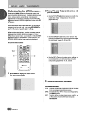
... are selected in ○p○ut○s This function enables you want to create a label for each of the 4 inputs. 1,9 MUTING RECEIVER EDIT/ LEARN SOURCE POWER DVD TOP MENU MENU 1 % % TV/SAT/DTV/DVD MENU % SAT/DTV GUIDE SET/ SELECT % (SAT)/DTV INFO FAVORITES 7 3 ¡ 2,3,4,5, 6,7,8 1 Press MENU to display the menu...
... are selected in ○p○ut○s This function enables you want to create a label for each of the 4 inputs. 1,9 MUTING RECEIVER EDIT/ LEARN SOURCE POWER DVD TOP MENU MENU 1 % % TV/SAT/DTV/DVD MENU % SAT/DTV GUIDE SET/ SELECT % (SAT)/DTV INFO FAVORITES 7 3 ¡ 2,3,4,5, 6,7,8 1 Press MENU to display the menu...
Owner's Manual
Page 32
... to the previous menu screen, use the menu screens 1,3 2 CH RETURN CH VOL MUTING RECEIVER EDIT/ LEARN TV/SAT/DTV/DVD MENU SOURCE SAT/DTV POWER % GUIDE DVD SET/ SELECT 2 TOP MENU (SAT)/DTV MENU % INFO FAVORITES 1 7 3 ¡ VCR REC 8 ¶ 4¢ ○ ○ ○ ○ ○ ○ ○ ○ ○...
... to the previous menu screen, use the menu screens 1,3 2 CH RETURN CH VOL MUTING RECEIVER EDIT/ LEARN TV/SAT/DTV/DVD MENU SOURCE SAT/DTV POWER % GUIDE DVD SET/ SELECT 2 TOP MENU (SAT)/DTV MENU % INFO FAVORITES 1 7 3 ¡ VCR REC 8 ¶ 4¢ ○ ○ ○ ○ ○ ○ ○ ○ ○...

