
Owner's Manual
Page 3
... be placed in a built-in a risk of time, unplug it will often require extensive work by following conditions: ÷ When the power-supply cord or plug is equipped with regard to proper grounding of the mast and supporting structure, grounding of the lead-in wire to an antenna...still fail to fit, contact your electrician to cords at plugs, convenience receptacles, and the point where they may result in performance - POWER-CORD PROTECTION - Power-supply cords should be installed in the cabinet are not sure of the type of any way. ÷ When the product exhibits a distinct ...
... be placed in a built-in a risk of time, unplug it will often require extensive work by following conditions: ÷ When the power-supply cord or plug is equipped with regard to proper grounding of the mast and supporting structure, grounding of the lead-in wire to an antenna...still fail to fit, contact your electrician to cords at plugs, convenience receptacles, and the point where they may result in performance - POWER-CORD PROTECTION - Power-supply cords should be installed in the cabinet are not sure of the type of any way. ÷ When the product exhibits a distinct ...
Owner's Manual
Page 6
ENGLISH CONTENTS ○ SAFETY PRECAUTIONS i BEFORE PROCEEDING 3 How to use this manual 3 Checking supplied accessories 5 PART NAMES AND FUNCTIONS .......... 6 Main unit 6 Remote control unit 7 Connection panel 8 INSTALLATION AND CONNECTIONS .... 9 Installation of the... How to route cables 16 SETTING UP THE SYSTEM 17 Setup after connection 17 OPERATIONS 20 Selecting an input source 20 Screen size selection 22 POWER SAVE 26 Labeling the Inputs 27 ○ ○ ○ ○ ○ ○ ○ ○ ○ ○ ○ ○ ○ ○ &#...
ENGLISH CONTENTS ○ SAFETY PRECAUTIONS i BEFORE PROCEEDING 3 How to use this manual 3 Checking supplied accessories 5 PART NAMES AND FUNCTIONS .......... 6 Main unit 6 Remote control unit 7 Connection panel 8 INSTALLATION AND CONNECTIONS .... 9 Installation of the... How to route cables 16 SETTING UP THE SYSTEM 17 Setup after connection 17 OPERATIONS 20 Selecting an input source 20 Screen size selection 22 POWER SAVE 26 Labeling the Inputs 27 ○ ○ ○ ○ ○ ○ ○ ○ ○ ○ ○ ○ ○ ○ &#...
Owner's Manual
Page 9
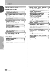
...ss○or○ie○s○ ○ ○ ○ ○ ○ ○ Check that the following accessories were supplied. 1 Power cord ○ ○ ○ ○ 6 Bead band x 2 ○ ○ ○ ○ ○ ○...; ○ ○ ○ 2 Remote control unit 7 4 1 2 MODESCREEN STA/IVNNCTDPRVUBTY/S/COABTNL DTV/LDDVD 3 POWER AUTO 4 AUDIO INPUT CC STILL RECEIVER DISPLAY 1 5 2 3 CLEAR MOVDIEEW DTV ¶ 8 6 0 9 CH RETUCRHN 8 POWSEORULRECAEREDNIT/ % % MTEONPUDMVENDU 1 SELSEECTT/ ...
...ss○or○ie○s○ ○ ○ ○ ○ ○ ○ Check that the following accessories were supplied. 1 Power cord ○ ○ ○ ○ 6 Bead band x 2 ○ ○ ○ ○ ○ ○...; ○ ○ ○ 2 Remote control unit 7 4 1 2 MODESCREEN STA/IVNNCTDPRVUBTY/S/COABTNL DTV/LDDVD 3 POWER AUTO 4 AUDIO INPUT CC STILL RECEIVER DISPLAY 1 5 2 3 CLEAR MOVDIEEW DTV ¶ 8 6 0 9 CH RETUCRHN 8 POWSEORULRECAEREDNIT/ % % MTEONPUDMVENDU 1 SELSEECTT/ ...
Owner's Manual
Page 12
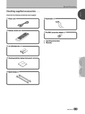
... selector switch Depending on the connections made at the same time. However, if simultaneous signals are also CONTROL terminals for connection of PIONEER components with component video output (page 10). 7 INPUT1 For connection of components that have an S-video or composite video output jack... synchronization signal. When the output impedance of the component's synchronization signal is given priority (page 10). 8 AC INLET Use to connect the supplied power cord to an AC outlet (page 15). ○ ○ ○ ○ 8 En This terminal is possible to have connections ...
... selector switch Depending on the connections made at the same time. However, if simultaneous signals are also CONTROL terminals for connection of PIONEER components with component video output (page 10). 7 INPUT1 For connection of components that have an S-video or composite video output jack... synchronization signal. When the output impedance of the component's synchronization signal is given priority (page 10). 8 AC INLET Use to connect the supplied power cord to an AC outlet (page 15). ○ ○ ○ ○ 8 En This terminal is possible to have connections ...

Owner's Manual
Page 19
...sensor on another unit, the remote sensor of connected PIONEER components that indicated (AC 120 V, 60 Hz) as this may cause fire or electric shock. ÷ For the plasma display, a three-core power cord with a ground terminal is made , remote ...9675; ○ ○ ○ ○ ○ ○ ○ ○ ○ ○ ○ ○ 15 En If you use a power source converter plug, use a power supply voltage other than that bear the Î logo mark is properly grounded. ENGLISH INSTALLATION AND CONNECTIONS C○o○nt○ro○l c○...
...sensor on another unit, the remote sensor of connected PIONEER components that indicated (AC 120 V, 60 Hz) as this may cause fire or electric shock. ÷ For the plasma display, a three-core power cord with a ground terminal is made , remote ...9675; ○ ○ ○ ○ ○ ○ ○ ○ ○ ○ ○ ○ 15 En If you use a power source converter plug, use a power supply voltage other than that bear the Î logo mark is properly grounded. ENGLISH INSTALLATION AND CONNECTIONS C○o○nt○ro○l c○...
Owner's Manual
Page 23
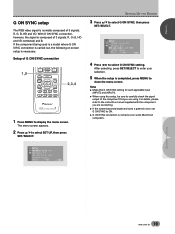
...RGB video signal is normally composed of 3 signals: R, G (G, HD and VD combined) and B. For details, please refer to the instruction manual supplied with the component you are using this setup, be sure to carefully check the signal output of G ON SYNC connection 1,5 CH VOL MUTING RECEIVER ...EDIT/ LEARN SOURCE POWER DVD TOP MENU MENU 1 8 % % TV/SAT/DTV/DVD MENU % SAT/DTV GUIDE SET/ SELECT % FAVORITES 7 3 VCR REC ¶ 4 (SAT)/DTV INFO ...
...RGB video signal is normally composed of 3 signals: R, G (G, HD and VD combined) and B. For details, please refer to the instruction manual supplied with the component you are using this setup, be sure to carefully check the signal output of G ON SYNC connection 1,5 CH VOL MUTING RECEIVER ...EDIT/ LEARN SOURCE POWER DVD TOP MENU MENU 1 8 % % TV/SAT/DTV/DVD MENU % SAT/DTV GUIDE SET/ SELECT % FAVORITES 7 3 VCR REC ¶ 4 (SAT)/DTV INFO ...
Owner's Manual
Page 43
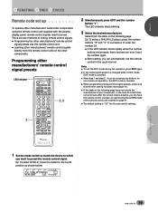
... EDIT mode is canceled. ÷ When programming remote control signal presets, make sure that the learn its signal using the remote control unit supplied with the plasma display panel, remote control signals need to the fourth position as shown below. Ex) To select a PHILIPS LD player, press... manufacturers' remote control signal presets LED indicator 2 TV CBL DTVDVD /VCR /SAT /LD STANDBY/ON INPUT 1 23 SCREEN MODE AUTO STILL 4 DISPLAY POWER AUDIO INPUT RECEIVER CC CLEAR DTV VIEW MODE 123 456 789 ¶ 0 CH ENTER CH RETURN CH VOL MUTING RECEIVER EDIT/ LEARN SOURCE...
... EDIT mode is canceled. ÷ When programming remote control signal presets, make sure that the learn its signal using the remote control unit supplied with the plasma display panel, remote control signals need to the fourth position as shown below. Ex) To select a PHILIPS LD player, press... manufacturers' remote control signal presets LED indicator 2 TV CBL DTVDVD /VCR /SAT /LD STANDBY/ON INPUT 1 23 SCREEN MODE AUTO STILL 4 DISPLAY POWER AUDIO INPUT RECEIVER CC CLEAR DTV VIEW MODE 123 456 789 ¶ 0 CH ENTER CH RETURN CH VOL MUTING RECEIVER EDIT/ LEARN SOURCE...
Owner's Manual
Page 53
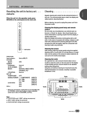
...Wipe the display and remote control gently with a hard object. Cleaning the screen After dusting, wipe the screen gently using the supplied cleaning cloth or a soft cloth. Using the unit without cleaning it with a dry soft cloth. The recommended way to clean ...selector : Set to INPUT1 PICTURE MODE : STD SCREEN Parameters : Set to 0 AUTO SCREEN : OFF MODE : NATURAL WIDE (VIDEO) ORIGINAL (PC)* V.POSITION : Set to 0 SET UP POWER SAVE : OFF SIGNAL/FORMAT: - / COMPONENT2 (INPUT2) PC / RGB (INPUT3) PC / RGB (INPUT4) G ON SYNC: OFF (INPUT3) OFF (INPUT4) STILL : OFF * When...
...Wipe the display and remote control gently with a hard object. Cleaning the screen After dusting, wipe the screen gently using the supplied cleaning cloth or a soft cloth. Using the unit without cleaning it with a dry soft cloth. The recommended way to clean ...selector : Set to INPUT1 PICTURE MODE : STD SCREEN Parameters : Set to 0 AUTO SCREEN : OFF MODE : NATURAL WIDE (VIDEO) ORIGINAL (PC)* V.POSITION : Set to 0 SET UP POWER SAVE : OFF SIGNAL/FORMAT: - / COMPONENT2 (INPUT2) PC / RGB (INPUT3) PC / RGB (INPUT4) G ON SYNC: OFF (INPUT3) OFF (INPUT4) STILL : OFF * When...

Owner's Manual
Page 58
... ... 1 Vp-p/75 Ω/negative sync. 2 Component video signal Y ... 1 Vp-p/75 Ω/negative sync. monaural mini jack (x2) Accessories Power cord 1 Pin/BNC conversion adaptor 1 Remote control unit 1 AA (LR6) batteries 2 Cleaning cloth 1 Speed clamp 2 Bead band 2 Warranty 1 Operating...9675;ic○at○io○ns General Light emission panel 50 inch plasma display panel Number of pixels 1280 x 768 Power supply AC 120 V, 60 Hz Power consumption 468 W Standby power consumption 0.6 W External dimensions ........ 1218 (W) x 714 (H) x 98 (D) mm 47-31/32 (W) x 28-1/8 (H) ...
... ... 1 Vp-p/75 Ω/negative sync. 2 Component video signal Y ... 1 Vp-p/75 Ω/negative sync. monaural mini jack (x2) Accessories Power cord 1 Pin/BNC conversion adaptor 1 Remote control unit 1 AA (LR6) batteries 2 Cleaning cloth 1 Speed clamp 2 Bead band 2 Warranty 1 Operating...9675;ic○at○io○ns General Light emission panel 50 inch plasma display panel Number of pixels 1280 x 768 Power supply AC 120 V, 60 Hz Power consumption 468 W Standby power consumption 0.6 W External dimensions ........ 1218 (W) x 714 (H) x 98 (D) mm 47-31/32 (W) x 28-1/8 (H) ...


