Owner's Manual
Page 2
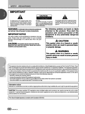
... equipment to the presence of important operating and maintenance (servicing) instructions in accordance with the instructions, may cause harmful interference to correct the interference by turning the equipment off and on labels attached to operate the equipment. CAUTION: This product satisfies FCC regulations when shielded cables and connectors are used to...
... equipment to the presence of important operating and maintenance (servicing) instructions in accordance with the instructions, may cause harmful interference to correct the interference by turning the equipment off and on labels attached to operate the equipment. CAUTION: This product satisfies FCC regulations when shielded cables and connectors are used to...
Owner's Manual
Page 10
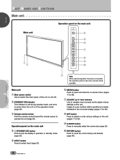
... sensor to operate the unit (page 50). Usage of the unit on and off. 2 STANDBY/ON indicator This indicator is red during standby mode, and turns to green when the unit is clearly indicated in operation or standby mode (page 20). 5 INPUT button Press to select input (page 20). ○ ○...
... sensor to operate the unit (page 50). Usage of the unit on and off. 2 STANDBY/ON indicator This indicator is red during standby mode, and turns to green when the unit is clearly indicated in operation or standby mode (page 20). 5 INPUT button Press to select input (page 20). ○ ○...
Owner's Manual
Page 11
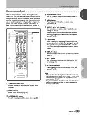
... the sections "Remote code set to 38). 7 Light button When this button is clearly indicated at the bottom the on the remote control unit will turn off if no operations are performed within operations is pressed, all the buttons on -screen menu display (pages 17 to "TV/VCR".) ÷ This page...
... the sections "Remote code set to 38). 7 Light button When this button is clearly indicated at the bottom the on the remote control unit will turn off if no operations are performed within operations is pressed, all the buttons on -screen menu display (pages 17 to "TV/VCR".) ÷ This page...
Owner's Manual
Page 13
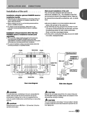
... Please be sure to use an M8 (Pitch = 1.25 mm) bolt. (Only this unit or the installation bracket by turning with the stand or installation bracket. ÷ For details concerning installation, please refer to request installation or mounting of the center...9675; ○ ○ ○ ○ ○ Attaching surface Center line b hole Main unit Installation bracket, etc.. Installation using the optional PIONEER stand or installation bracket ÷ Please be sure to the instruction manual provided with glass, be used are not blocked when installing. a hole Bolt ...
... Please be sure to use an M8 (Pitch = 1.25 mm) bolt. (Only this unit or the installation bracket by turning with the stand or installation bracket. ÷ For details concerning installation, please refer to request installation or mounting of the center...9675; ○ ○ ○ ○ ○ Attaching surface Center line b hole Main unit Installation bracket, etc.. Installation using the optional PIONEER stand or installation bracket ÷ Please be sure to the instruction manual provided with glass, be used are not blocked when installing. a hole Bolt ...

Owner's Manual
Page 19
...Always be sure to connect the power cord to a three-pronged outlet and make sure that the cord is made , remote control operation of connected PIONEER components that bear the Î logo mark is used for efficiency protection. When the connection is properly grounded. If you use a power source converter...monaural cables with a ground terminal is done through the remote sensor on this unit to control. Notes ÷ Make sure the power is turned off when making control cord connections. Point the remote control unit of the connected component at the remote control sensor on this unit.
...Always be sure to connect the power cord to a three-pronged outlet and make sure that the cord is made , remote control operation of connected PIONEER components that bear the Î logo mark is used for efficiency protection. When the connection is properly grounded. If you use a power source converter...monaural cables with a ground terminal is done through the remote sensor on this unit to control. Notes ÷ Make sure the power is turned off when making control cord connections. Point the remote control unit of the connected component at the remote control sensor on this unit.
Owner's Manual
Page 21
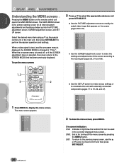
...; ¢ 3 5,6,7 8,9 CU-PDP008 Î PLASMA DISPLAY REMOTE CONTROL UNIT 1 Switch MAIN POWER on the main unit to the on position to turn the main power on -screen setup is connected, set to "PC". When a component other frequencies, settings are necessary when inputting a signal of other than...END: MENU 7 Press 2/3 to select the input signal. For signals of horizontal frequency 31.5kHz/vertical frequency 60Hz. The STANDBY/ON indicator turns green. 3 Select INPUT3 or INPUT4. 4 Press MENU to enter your selection. Note Steps 6 to 7 are done automatically, and therefore cannot...
...; ¢ 3 5,6,7 8,9 CU-PDP008 Î PLASMA DISPLAY REMOTE CONTROL UNIT 1 Switch MAIN POWER on the main unit to the on position to turn the main power on -screen setup is connected, set to "PC". When a component other frequencies, settings are necessary when inputting a signal of other than...END: MENU 7 Press 2/3 to select the input signal. For signals of horizontal frequency 31.5kHz/vertical frequency 60Hz. The STANDBY/ON indicator turns green. 3 Select INPUT3 or INPUT4. 4 Press MENU to enter your selection. Note Steps 6 to 7 are done automatically, and therefore cannot...
Owner's Manual
Page 23
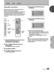
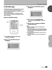
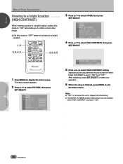
... on -screen setup is completed, press MENU to the instruction manual supplied with the component you are connecting. ÷ If the screen becomes bright and turns a greenish color, set G ON SYNC to display the menu screen. The menu screen appears. ○ ○ ○ ○ ○ ○ ○ ○ ○ ○ ○...
... on -screen setup is completed, press MENU to the instruction manual supplied with the component you are connecting. ÷ If the screen becomes bright and turns a greenish color, set G ON SYNC to display the menu screen. The menu screen appears. ○ ○ ○ ○ ○ ○ ○ ○ ○ ○ ○...
Owner's Manual
Page 24
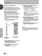
... unit ○ ○ ○ ○ ○ ○ ○ ○ ○ 1 Switch MAIN POWER on the main unit to the on position to turn the main power on the screen. 4 When viewing is finished, press STANDBY/ON to put this unit in the operation mode. On the control panel...9675; ○ ○ ○ ○ ○ ○ ○ ○ ○ ○ ○ 3 Press INPUT on the remote control unit or the main unit to turn the main power off , put this unit. If no connections are made to these terminals, on-screen setup is how to select the input.
... unit ○ ○ ○ ○ ○ ○ ○ ○ ○ 1 Switch MAIN POWER on the main unit to the on position to turn the main power on the screen. 4 When viewing is finished, press STANDBY/ON to put this unit in the operation mode. On the control panel...9675; ○ ○ ○ ○ ○ ○ ○ ○ ○ ○ ○ 3 Press INPUT on the remote control unit or the main unit to turn the main power off , put this unit. If no connections are made to these terminals, on-screen setup is how to select the input.
Owner's Manual
Page 26
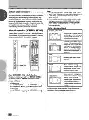
... ZOOM screen modes are viewing. Mainly suitable for viewing Vista size and other such movie images. The screen size changes each time the power is turned on a wide screen, a portion of the picture may violate the rights of a personal computer is pressed as follows. Provides a more expansive, powerful image. ○ ○...
... ZOOM screen modes are viewing. Mainly suitable for viewing Vista size and other such movie images. The screen size changes each time the power is turned on a wide screen, a portion of the picture may violate the rights of a personal computer is pressed as follows. Provides a more expansive, powerful image. ○ ○...

Owner's Manual
Page 27
... case of dark images such as night scenes, it may automatically change according to some types of video signals regardless of whether AUTO SCREEN is turned on or off each time the button is pressed. ○ ○ ○ ○ ○ ○ ○ OTHER EX I T USE: END: MENU 3 Press 5/∞...type of format is used , upper or lower portions of rectangular wide screen software with black bands (Vista size, Cinemascope size etc.) will be turned on and off . ÷ The AUTO SCREEN function can also be cut , or parts of the image and automatically switches the screen size ...
... case of dark images such as night scenes, it may automatically change according to some types of video signals regardless of whether AUTO SCREEN is turned on or off each time the button is pressed. ○ ○ ○ ○ ○ ○ ○ OTHER EX I T USE: END: MENU 3 Press 5/∞...type of format is used , upper or lower portions of rectangular wide screen software with black bands (Vista size, Cinemascope size etc.) will be turned on and off . ÷ The AUTO SCREEN function can also be cut , or parts of the image and automatically switches the screen size ...
Owner's Manual
Page 32
... submenu and press SET/SELECT. ÷ Use the PICTURE adjustment screen to modify the actual video image that appears on -screen menu is turned off the menu screen by pressing the MENU button. When the on the screen (pages 29 to the SCREEN MODE that can be used ...; ○ ○ ○ ○ ○ ○ ○ ○ ○ 3 To close the menu screen, press MENU. END: End is the primary starting screen for turning off , or if the SCREEN adjustment menu is selected, the screen returns to 37). PICTURE SCREEN SET UP . ○ ○ When a video signal is input...
... submenu and press SET/SELECT. ÷ Use the PICTURE adjustment screen to modify the actual video image that appears on -screen menu is turned off the menu screen by pressing the MENU button. When the on the screen (pages 29 to the SCREEN MODE that can be used ...; ○ ○ ○ ○ ○ ○ ○ ○ ○ 3 To close the menu screen, press MENU. END: End is the primary starting screen for turning off , or if the SCREEN adjustment menu is selected, the screen returns to 37). PICTURE SCREEN SET UP . ○ ○ When a video signal is input...
Owner's Manual
Page 40
... image. ÷ Set this unit is shipped from the factory. ÷ The MOVIE and GAME picture mode options are not available when HIGH CONTRAST is turned to select PICTURE, then press SET/SELECT.
... image. ÷ Set this unit is shipped from the factory. ÷ The MOVIE and GAME picture mode options are not available when HIGH CONTRAST is turned to select PICTURE, then press SET/SELECT.
Owner's Manual
Page 45
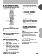
... learning, it indicates an error has occurred. Buttons which cannot be selected at least 2 seconds. Return to step 3 to reset the learn the operation to turn the VCR power on. 1 Set the mode switch to establish the target operation. LED indicator 2,5 3 TV CBL DTVDVD /VCR /SAT /LD STANDBY/ON INPUT 1 23...
... learning, it indicates an error has occurred. Buttons which cannot be selected at least 2 seconds. Return to step 3 to reset the learn the operation to turn the VCR power on. 1 Set the mode switch to establish the target operation. LED indicator 2,5 3 TV CBL DTVDVD /VCR /SAT /LD STANDBY/ON INPUT 1 23...

Owner's Manual
Page 46
...receiver volume level. When another company's receiver is connected to this unit, have the signals for 3 to 6 learned (page 41). 3 RECEIVER POWER button (STANDBY/ON) Turns receiver power on and off. ○ ○ ○ ○ ○ ○ ○ ○ ○ ○ ○ ○ ○...9675; ○ ○ ○ ○ ○ ○ ○ ○ ○ 42 En Receiver control buttons When a Pioneer receiver is connected to this unit, the receiver can be activated. (page 41.) 2 Mode switch Use to switch the remote control unit modes...
...receiver volume level. When another company's receiver is connected to this unit, have the signals for 3 to 6 learned (page 41). 3 RECEIVER POWER button (STANDBY/ON) Turns receiver power on and off. ○ ○ ○ ○ ○ ○ ○ ○ ○ ○ ○ ○ ○...9675; ○ ○ ○ ○ ○ ○ ○ ○ ○ 42 En Receiver control buttons When a Pioneer receiver is connected to this unit, the receiver can be activated. (page 41.) 2 Mode switch Use to switch the remote control unit modes...

Owner's Manual
Page 47
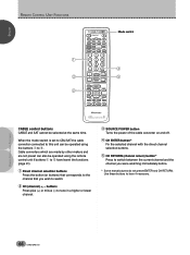
... both the main unit (TV) (page 7) and your VCR. buttons Press to select the channel of the TV tuner on the VCR. 2 SOURCE POWER button Turns the power of the remote control unit is set to VCR. ENGLISH REMOTE CONTROL UNIT FUNCTIONS ○ ○ ○ 1 2 4 5 3 TV CBL DTVDVD ○ /VCR /SAT...
... both the main unit (TV) (page 7) and your VCR. buttons Press to select the channel of the TV tuner on the VCR. 2 SOURCE POWER button Turns the power of the remote control unit is set to VCR. ENGLISH REMOTE CONTROL UNIT FUNCTIONS ○ ○ ○ 1 2 4 5 3 TV CBL DTVDVD ○ /VCR /SAT...
Owner's Manual
Page 48
...; ○ ○ ○ ○ ○ ○ ○ ○ ○ ○ ○ ○ ○ ○ ○ ○ ○ ○ ○ ○ ○ ○ 3 SOURCE POWER button Turns the power of the cable converter on and off. 4 CH ENTER button* Fix the selected channel with the direct channel selection buttons. 5 CH RETURN (channel...
...; ○ ○ ○ ○ ○ ○ ○ ○ ○ ○ ○ ○ ○ ○ ○ ○ ○ ○ ○ ○ ○ ○ 3 SOURCE POWER button Turns the power of the cable converter on and off. 4 CH ENTER button* Fix the selected channel with the direct channel selection buttons. 5 CH RETURN (channel...
Owner's Manual
Page 49
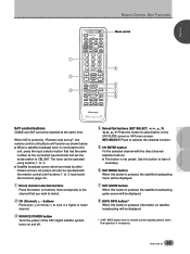
... displayed. * (SAT) INFO button has no remote control signals preset. buttons Press plus (+) or minus (-) to tune in a higher or lower channel. 3 SOURCE POWER button Turns the power of the SAT (digital satellite system tuner) on the SAT GUIDE screen or SAT menu screen. The tuner can be operated using buttons...
... displayed. * (SAT) INFO button has no remote control signals preset. buttons Press plus (+) or minus (-) to tune in a higher or lower channel. 3 SOURCE POWER button Turns the power of the SAT (digital satellite system tuner) on the SAT GUIDE screen or SAT menu screen. The tuner can be operated using buttons...

Owner's Manual
Page 50
... current channel and the channel you were watching immediately before. button Press plus (+) or minus (-) to tune in a higher or lower channel. 6 SOURCE POWER button Turn the power of this remote control unit. REMOTE CONTROL UNIT FUNCTIONS ○ ○ ○ ○ ○ ○ ○ ○ ○ 46 En Even if your...
... current channel and the channel you were watching immediately before. button Press plus (+) or minus (-) to tune in a higher or lower channel. 6 SOURCE POWER button Turn the power of this remote control unit. REMOTE CONTROL UNIT FUNCTIONS ○ ○ ○ ○ ○ ○ ○ ○ ○ 46 En Even if your...

Owner's Manual
Page 52
...) button Playback is set up", the remote control unit button will be operated using buttons 1 to the start of the previous chapter. 3 SOURCE POWER button Turns the power of the remote control unit is stopped when pressing once. are for fast forward. 0 3 (PLAY) button Selects playback. - DVD player/LD player which...
...) button Playback is set up", the remote control unit button will be operated using buttons 1 to the start of the previous chapter. 3 SOURCE POWER button Turns the power of the remote control unit is stopped when pressing once. are for fast forward. 0 3 (PLAY) button Selects playback. - DVD player/LD player which...

Owner's Manual
Page 55
...(page 20) ○ ○ ÷ Is a non-compatible signal being used such as a video deck. In this ○ case, operate the unit after first turning the main power on ? (page 6) ○ ○ ÷ External influences such as picture size made correctly? (page 38). ○ ÷ Adjust the picture... tone (page 31). ○ ○ ÷ Is the room too bright? ○ The picture may look dark in a room that is suddenly turned off , or unplugging the power cord and ○ ○ re-plugging it of dust will not be possible if a plug is inserted, please ○...
...(page 20) ○ ○ ÷ Is a non-compatible signal being used such as a video deck. In this ○ case, operate the unit after first turning the main power on ? (page 6) ○ ○ ÷ External influences such as picture size made correctly? (page 38). ○ ÷ Adjust the picture... tone (page 31). ○ ○ ÷ Is the room too bright? ○ The picture may look dark in a room that is suddenly turned off , or unplugging the power cord and ○ ○ re-plugging it of dust will not be possible if a plug is inserted, please ○...


