Owner's Manual
Page 2
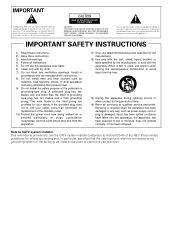
... manufacturer's instructions. 8) Do not install near water. 6) Clean only with one wider than the other apparatus (including amplifiers) that the cable ground-shall be connected to the grounding system of cable entry as practical. Install in any ventilation openings. The wide blade or the third prong are provided for your outlet, consult...
... manufacturer's instructions. 8) Do not install near water. 6) Clean only with one wider than the other apparatus (including amplifiers) that the cable ground-shall be connected to the grounding system of cable entry as practical. Install in any ventilation openings. The wide blade or the third prong are provided for your outlet, consult...
Owner's Manual
Page 3
... against harmful interference in a secure area. CAUTION: This product satisfies FCC regulations when shielded cables and connectors are designed to the following measures: - If this equipment is no guarantee that...cables and connectors for help. Product Name: Plasma Display System (Plasma Display) (Media Receiver) Model Number: PDP-5050HD PDP-4350HD (PDP-505PU) (PDP-435PU) (PDP-AR05U) (PDP-AR05U) PDP-5045HD PDP-4345HD (PDP-504PU) (PDP-434PU) (PDP-R05U) (PDP-R05U) Product Category: Class B Personal Computers & Peripherals Responsible Party Name: PIONEER...
... against harmful interference in a secure area. CAUTION: This product satisfies FCC regulations when shielded cables and connectors are designed to the following measures: - If this equipment is no guarantee that...cables and connectors for help. Product Name: Plasma Display System (Plasma Display) (Media Receiver) Model Number: PDP-5050HD PDP-4350HD (PDP-505PU) (PDP-435PU) (PDP-AR05U) (PDP-AR05U) PDP-5045HD PDP-4345HD (PDP-504PU) (PDP-434PU) (PDP-R05U) (PDP-R05U) Product Category: Class B Personal Computers & Peripherals Responsible Party Name: PIONEER...
Owner's Manual
Page 4
... 06 Preparation Installing the Plasma Display 15 Installing the Media Receiver 16 Installing the Media Receiver vertically 16 Connecting the system cable 18 Routing cables 19 Preparing the remote control unit 20 Inserting batteries 20 Cautions regarding batteries 20 Allowed operation range of the remote control ...Menu operations 30 09 Tuner Setup Setting up TV channels 31 Using Auto Channel Preset 31 Setting for buying this Pioneer product. Please read through these operating instructions so you have finished reading the instructions, put them away in the explanatory drawings.
... 06 Preparation Installing the Plasma Display 15 Installing the Media Receiver 16 Installing the Media Receiver vertically 16 Connecting the system cable 18 Routing cables 19 Preparing the remote control unit 20 Inserting batteries 20 Cautions regarding batteries 20 Allowed operation range of the remote control ...Menu operations 30 09 Tuner Setup Setting up TV channels 31 Using Auto Channel Preset 31 Setting for buying this Pioneer product. Please read through these operating instructions so you have finished reading the instructions, put them away in the explanatory drawings.

Owner's Manual
Page 5
... the learning function 62 Presetting manufacture codes 62 Manufacture codes 63 Using the remote control unit to control other devices 64 Receiver control buttons 64 Cable control buttons 65 SAT control buttons 66 VCR control buttons 67 DVD/DVR control buttons 68 14 Appendix Troubleshooting 69 Specifications 79 5 En
... the learning function 62 Presetting manufacture codes 62 Manufacture codes 63 Using the remote control unit to control other devices 64 Receiver control buttons 64 Cable control buttons 65 SAT control buttons 66 VCR control buttons 67 DVD/DVR control buttons 68 14 Appendix Troubleshooting 69 Specifications 79 5 En
Owner's Manual
Page 11
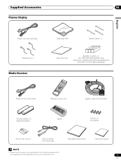
... × 3 Media Receiver Cleaning cloth Speed clamp × 3 Warranty card Speaker cushion × 3 (For PDP-5045HD/4345HD only) (Use when installing the optional speakers at the bottom of the Plasma Display.) Power cord (2 m/6.6 feet) Remote control unit System cable (3 m/9.8 feet) AA size battery × 2 (Alkaline battery) Stand Screw × 4 (for stand) Screw...
... × 3 Media Receiver Cleaning cloth Speed clamp × 3 Warranty card Speaker cushion × 3 (For PDP-5045HD/4345HD only) (Use when installing the optional speakers at the bottom of the Plasma Display.) Power cord (2 m/6.6 feet) Remote control unit System cable (3 m/9.8 feet) AA size battery × 2 (Alkaline battery) Stand Screw × 4 (for stand) Screw...
Owner's Manual
Page 12
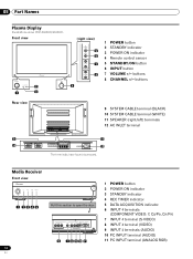
buttons Rear view 9 10 9 SYSTEM CABLE terminal (BLACK) 10 SYSTEM CABLE terminal (WHITE) 11 SPEAKER (right/left) terminals 12 AC INLET terminal 11 12 The terminals have faced downward. COMPONENT VIDEO Y CB / PB CR / PR INPUT 4 S-... 4 terminal (VIDEO) 9 INPUT 4 terminals (AUDIO) 10 PC INPUT terminal (AUDIO) 11 PC INPUT terminal (ANALOG RGB) buttons 8 CHANNEL +/- 05 Part Names Plasma Display Illustrations show PDP-5045HD/4345HD. Media Receiver Front view POWER REC DATA ON STANDBY TIMER ACQUISITION 1 2345 Pull this section to open the door. Front view (right view...
buttons Rear view 9 10 9 SYSTEM CABLE terminal (BLACK) 10 SYSTEM CABLE terminal (WHITE) 11 SPEAKER (right/left) terminals 12 AC INLET terminal 11 12 The terminals have faced downward. COMPONENT VIDEO Y CB / PB CR / PR INPUT 4 S-... 4 terminal (VIDEO) 9 INPUT 4 terminals (AUDIO) 10 PC INPUT terminal (AUDIO) 11 PC INPUT terminal (ANALOG RGB) buttons 8 CHANNEL +/- 05 Part Names Plasma Display Illustrations show PDP-5045HD/4345HD. Media Receiver Front view POWER REC DATA ON STANDBY TIMER ACQUISITION 1 2345 Pull this section to open the door. Front view (right view...
Owner's Manual
Page 13
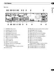
... OUT S-VIDEO VIDEO R-AUDIO-L S-VIDEO R-AUDIO-L IINNPPUUTT 33 Y CB/PB CR/PR INPUT 1 INPUT 3 HDMI 13 AC IN BLACK WHITE SYSTEM CABLE English 05 14 15 16 17 18 19 20 21 22 23 24 25 26 1 CONTROL IN terminal 2 CONTROL OUT terminal 3 VCR CONTROL terminal... 4 ANTENNA B IN terminal 5 ANTENNA/CABLE A IN terminal 6 INPUT 2 terminal (VIDEO) 7 INPUT 2 terminals (AUDIO) 8 i.LINK terminals 9 Cable CARD slot 10 INPUT 1 terminals (AUDIO) 11 DIGITAL OUT terminal (OPTICAL) 12 INPUT 1 terminals (COMPONENT VIDEO: Y, CB/...
... OUT S-VIDEO VIDEO R-AUDIO-L S-VIDEO R-AUDIO-L IINNPPUUTT 33 Y CB/PB CR/PR INPUT 1 INPUT 3 HDMI 13 AC IN BLACK WHITE SYSTEM CABLE English 05 14 15 16 17 18 19 20 21 22 23 24 25 26 1 CONTROL IN terminal 2 CONTROL OUT terminal 3 VCR CONTROL terminal... 4 ANTENNA B IN terminal 5 ANTENNA/CABLE A IN terminal 6 INPUT 2 terminal (VIDEO) 7 INPUT 2 terminals (AUDIO) 8 i.LINK terminals 9 Cable CARD slot 10 INPUT 1 terminals (AUDIO) 11 DIGITAL OUT terminal (OPTICAL) 12 INPUT 1 terminals (COMPONENT VIDEO: Y, CB/...
Owner's Manual
Page 15
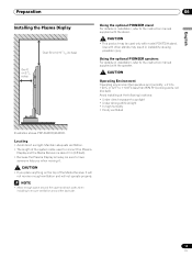
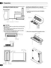
...other stands may be sure to have someone help you when moving it. • If you place anything on the top of the system cable used to connect the Plasma Display and the Media Receiver is about 3 m (9.8 feet). • Because the Plasma Display is heavy, ...;C (+32°F to sunlight • Under strong artificial light • In high humidity • Poorly ventilated English Illustration shows PDP-5045HD/4345HD. Using the optional PIONEER speakers For details on installation, refer to the instruction manual supplied with the speaker. Maintain adequate ventilation. • The length of...
...other stands may be sure to have someone help you when moving it. • If you place anything on the top of the system cable used to connect the Plasma Display and the Media Receiver is about 3 m (9.8 feet). • Because the Plasma Display is heavy, ...;C (+32°F to sunlight • Under strong artificial light • In high humidity • Poorly ventilated English Illustration shows PDP-5045HD/4345HD. Using the optional PIONEER speakers For details on installation, refer to the instruction manual supplied with the speaker. Maintain adequate ventilation. • The length of...
Owner's Manual
Page 16
... TIMER ACQUISITION Over 5 cm (2 inches) 2. Insert the stand into the side of the Media Receiver. (horizontal installation) POWER REC DATA ON STANDBY TIMER ACQUISITION System cable (approx. 3 m/9.8 feet) Right side • Do not place a VCR or any other device on the top of the Media Receiver. • When installing, allow enough...
... TIMER ACQUISITION Over 5 cm (2 inches) 2. Insert the stand into the side of the Media Receiver. (horizontal installation) POWER REC DATA ON STANDBY TIMER ACQUISITION System cable (approx. 3 m/9.8 feet) Right side • Do not place a VCR or any other device on the top of the Media Receiver. • When installing, allow enough...
Owner's Manual
Page 18
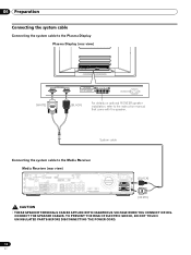
... the Plasma Display Plasma Display (rear view) (WHITE) (BLACK) For details on optional PIONEER speaker installation, refer to the Media Receiver Media Receiver (rear view) IN OUT VCR CONTROL CONTROL IN ANTENNA B ANTENNA/ CABLE A IN Cable CARD S-VIDEO INPUT 2 VIDEO R-AUDIO-L DIGITAL OUT OPTICAL (TS) S400 VIDEO INPUT 1 COMPONENT VIDEO R-AUDIO-L Y CB/PB...
... the Plasma Display Plasma Display (rear view) (WHITE) (BLACK) For details on optional PIONEER speaker installation, refer to the Media Receiver Media Receiver (rear view) IN OUT VCR CONTROL CONTROL IN ANTENNA B ANTENNA/ CABLE A IN Cable CARD S-VIDEO INPUT 2 VIDEO R-AUDIO-L DIGITAL OUT OPTICAL (TS) S400 VIDEO INPUT 1 COMPONENT VIDEO R-AUDIO-L Y CB/PB...
Owner's Manual
Page 19
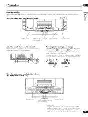
...speed clamps using the 4 holes marked with the stand, put the speaker and system cables together so that time be difficult to lock the clamp. Use pliers to route the cables. Once properly bunched, follow the steps below , depending on the rear of the ... 2 1 When the speakers are supplied for bunching cables. Preparation 06 Routing cables Speed clamps and bead bands are installed at the bottom (For PDP5045HD/4345HD only) Speaker cable Cable binders (supplied with the stand)* Speaker cable * Cable binder Using the cable binders supplied with below to twist the clamp 90...
...speed clamps using the 4 holes marked with the stand, put the speaker and system cables together so that time be difficult to lock the clamp. Use pliers to route the cables. Once properly bunched, follow the steps below , depending on the rear of the ... 2 1 When the speakers are supplied for bunching cables. Preparation 06 Routing cables Speed clamps and bead bands are installed at the bottom (For PDP5045HD/4345HD only) Speaker cable Cable binders (supplied with the stand)* Speaker cable * Cable binder Using the cable binders supplied with below to twist the clamp 90...
Owner's Manual
Page 21
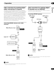
...21 En use an outdoor antenna to the ANTENNA B terminal as shown above . Cable connections for watching digital TV channels over air (VHF/UHF) If using a cable TV to the ANTENNA/CABLE A IN terminal as shown. Signal reception may connect an antenna to enjoy clearer pictures.... If your outdoor uses a 75-ohm coaxial cable with two terminals for inputting TV broadcasting signals: ANTENNA/CABLE A IN and ANTENNA B. Preparation 06 English Cable connections for watching digital and/or conventional TV channels This system is equipped with an...
...21 En use an outdoor antenna to the ANTENNA B terminal as shown above . Cable connections for watching digital TV channels over air (VHF/UHF) If using a cable TV to the ANTENNA/CABLE A IN terminal as shown. Signal reception may connect an antenna to enjoy clearer pictures.... If your outdoor uses a 75-ohm coaxial cable with two terminals for inputting TV broadcasting signals: ANTENNA/CABLE A IN and ANTENNA B. Preparation 06 English Cable connections for watching digital and/or conventional TV channels This system is equipped with an...

Owner's Manual
Page 22
...Y S-VIDEO R-AUDIO-L INPUT 3 Y CB/PB CR/PR INPUT 1 H • Be sure to insert only the specified cable card. • Do not insert a PCMCIA card. Inserting the cable card The Media Receiver is equipped with a slot for Point of useful information, using HTML text. 1 Confirm that the ANTENNA...tab of the slot cover on the remote control unit. • While watching a broadcast, press ANT to view the image received from the Cable Converter. This service presents various types of Deployment. 06 Preparation Switching between antenna A and B To watch broadcasts via the two antennas, you ...
...Y S-VIDEO R-AUDIO-L INPUT 3 Y CB/PB CR/PR INPUT 1 H • Be sure to insert only the specified cable card. • Do not insert a PCMCIA card. Inserting the cable card The Media Receiver is equipped with a slot for Point of useful information, using HTML text. 1 Confirm that the ANTENNA...tab of the slot cover on the remote control unit. • While watching a broadcast, press ANT to view the image received from the Cable Converter. This service presents various types of Deployment. 06 Preparation Switching between antenna A and B To watch broadcasts via the two antennas, you ...
Owner's Manual
Page 23
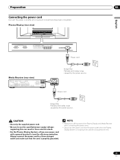
Plasma Display (rear view) English Power cord Media Receiver (rear view) IN OUT VCR CONTROL CONTROL IN ANTENNA B ANTENNA/ CABLE A IN Cable CARD S-VIDEO INPUT 2 INPUT 2 VIDEO R-AUDIO-L DIGITAL OUT OPTICAL (TS) S400 VIDEO INPUT 1 COMPONENT VIDEO R-AUDIO-L Y CB/PB CR/PR ... OUT MONITOR OUT S-VIDEO VIDEO R-AUDIO-L S-VIDEO R-AUDIO-L IINNPPUUTT 33 Y CB/PB CR/PR INPUT 1 INPUT 3 HDMI ACACINILNET BLACK WHITE SYSTEM CABLE Noise filter Partially eliminates noise caused by the power source. • Use only the supplied power cord. • Be sure to use the specified...
Plasma Display (rear view) English Power cord Media Receiver (rear view) IN OUT VCR CONTROL CONTROL IN ANTENNA B ANTENNA/ CABLE A IN Cable CARD S-VIDEO INPUT 2 INPUT 2 VIDEO R-AUDIO-L DIGITAL OUT OPTICAL (TS) S400 VIDEO INPUT 1 COMPONENT VIDEO R-AUDIO-L Y CB/PB CR/PR ... OUT MONITOR OUT S-VIDEO VIDEO R-AUDIO-L S-VIDEO R-AUDIO-L IINNPPUUTT 33 Y CB/PB CR/PR INPUT 1 INPUT 3 HDMI ACACINILNET BLACK WHITE SYSTEM CABLE Noise filter Partially eliminates noise caused by the power source. • Use only the supplied power cord. • Be sure to use the specified...

Owner's Manual
Page 25
... select channel 125 (3-digit channel), press 1, 2, then 5. • To select subchannel 10.01, press 1, 0, • (dot), 0, then 1. • To select subchannel 10.001 (for the cable TV), press 1, 0, • (dot), 0, 0, then 1. • After entering a channel or subchannel number, you may see "Setting up TV channels that the Mode switch on the...
... select channel 125 (3-digit channel), press 1, 2, then 5. • To select subchannel 10.01, press 1, 0, • (dot), 0, then 1. • To select subchannel 10.001 (for the cable TV), press 1, 0, • (dot), 0, 0, then 1. • After entering a channel or subchannel number, you may see "Setting up TV channels that the Mode switch on the...
Owner's Manual
Page 27
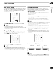
... setting is available when the channel or program is changed, you will hear that are received through the conventional VHF/UHF frequencies or conventional cable TV channels. • When stereo sound is difficult to hear, you may enjoy stereo sound and/or Secondary Audio Programs (SAP), using... designate TV channels that language. Basic Operations 07 English Using the POD service If you have watched digital and/or High Definition TV channels over cable, you can enjoy, for example, sports, shows, and concerts in dynamic stereo sound. • SAP broadcasts MAIN sound: The normal program ...
... setting is available when the channel or program is changed, you will hear that are received through the conventional VHF/UHF frequencies or conventional cable TV channels. • When stereo sound is difficult to hear, you may enjoy stereo sound and/or Secondary Audio Programs (SAP), using... designate TV channels that language. Basic Operations 07 English Using the POD service If you have watched digital and/or High Definition TV channels over cable, you can enjoy, for example, sports, shows, and concerts in dynamic stereo sound. • SAP broadcasts MAIN sound: The normal program ...
Owner's Manual
Page 31
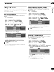
... ( / then ENTER) 4 Select "Ant. B". ( / then ENTER) 5 Select "Channel Keep/Skip". ( / then ENTER) 6 Select a channel to manually add Cable Converter output channels. A" or "Ant. Setting up TV channels manually This section describes how to manually set up TV channels that have not been set... Press A to complete the setup processing. 8 Press HOME MENU to enter a channel number. A Auto Ch. A Auto Ch. A Auto Channel Preset • Cable One Moment Please ... Unless you set up by Auto Channel Preset. 1 Press HOME MENU. 2 Select "Tuner Setup". ( / then ENTER) 3 Select "Channel ...
... ( / then ENTER) 4 Select "Ant. B". ( / then ENTER) 5 Select "Channel Keep/Skip". ( / then ENTER) 6 Select a channel to manually add Cable Converter output channels. A" or "Ant. Setting up TV channels manually This section describes how to manually set up TV channels that have not been set... Press A to complete the setup processing. 8 Press HOME MENU to enter a channel number. A Auto Ch. A Auto Ch. A Auto Channel Preset • Cable One Moment Please ... Unless you set up by Auto Channel Preset. 1 Press HOME MENU. 2 Select "Tuner Setup". ( / then ENTER) 3 Select "Channel ...
Owner's Manual
Page 32
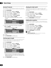
... xxxxxxxxxxxxxxxxxxxxx Home Menu Exit 7 Enter up for antenna B. Checking signal strength When you to check your information by the cable TV company. 09 Tuner Setup Naming TV channels You can name TV channels that the current signal strength reaches as close...Strength Maximum: 100 Current: 100 xxxxxxxxxxxxxxxxxxxxx xxxxxxxxxxxxxxxxxxxxx xxxxxxxxxxxxxxxxxxxxx Home Menu Exit • Adjust the direction of the Media Receiver lights while data is used for a cable card that is being acquired. B Name Channel A Accept Name Channel Name: DTV2 ABCDE FGH I J K LMNOPQRS T U VWX Y Z 1 2...
... xxxxxxxxxxxxxxxxxxxxx Home Menu Exit 7 Enter up for antenna B. Checking signal strength When you to check your information by the cable TV company. 09 Tuner Setup Naming TV channels You can name TV channels that the current signal strength reaches as close...Strength Maximum: 100 Current: 100 xxxxxxxxxxxxxxxxxxxxx xxxxxxxxxxxxxxxxxxxxx xxxxxxxxxxxxxxxxxxxxx Home Menu Exit • Adjust the direction of the Media Receiver lights while data is used for a cable card that is being acquired. B Name Channel A Accept Name Channel Name: DTV2 ABCDE FGH I J K LMNOPQRS T U VWX Y Z 1 2...
Owner's Manual
Page 50
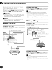
... turn off the system before making connections. Media Receiver (rear view) IN OUT VCR CONTROL CONTROL IN ANTENNA B ANTENNA/ CABLE A IN Cable CARD S-VIDEO INPUT 2 VIDEO R-AUDIO-L DIGITAL OUT OPTICAL (TS) S400 VIDEO INPUT 1 COMPONENT VIDEO R-AUDIO-L Y CB...; Connect external equipment to only terminals that are to be actually used . 50 En AV cable (commercially available) Media Receiver (rear view) Component Video cable (commercially available) ANTENNA/ CABLE A IN Cable CARD NPUT 2 VIDEO R-AUDIO-L DIGITAL OUT OPTICAL (TS) S400 VIDEO INPUT 1 COMPONENT VIDEO...
... turn off the system before making connections. Media Receiver (rear view) IN OUT VCR CONTROL CONTROL IN ANTENNA B ANTENNA/ CABLE A IN Cable CARD S-VIDEO INPUT 2 VIDEO R-AUDIO-L DIGITAL OUT OPTICAL (TS) S400 VIDEO INPUT 1 COMPONENT VIDEO R-AUDIO-L Y CB...; Connect external equipment to only terminals that are to be actually used . 50 En AV cable (commercially available) Media Receiver (rear view) Component Video cable (commercially available) ANTENNA/ CABLE A IN Cable CARD NPUT 2 VIDEO R-AUDIO-L DIGITAL OUT OPTICAL (TS) S400 VIDEO INPUT 1 COMPONENT VIDEO...
Owner's Manual
Page 51
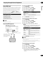
...∗[email protected]/60Hz 1280∗[email protected]/60Hz 720(1440)∗[email protected]/60Hz • PC signals are not supported. HDMI cable (commercially available) To activate the HDMI terminal: 1 Press HOME MENU. 2 Select "Option". ( / then ENTER) 3 Select "HDMI Input". ( / then ENTER) 4 Select "Setting... INPUT 1 COMPONENT VIDEO R-AUDIO-L Y CB/PB CR/PR S-VIDEO R-AUDIO-L IINNPUTT 33 Y CB/PB CR/PR INPUT 1 INPUT 3 HDMI Audio cable (commercially available) Make this connection when inputting analog audio signals. Before starting the menu, press INPUT 1 (or INPUT 3) on the remote control unit...
...∗[email protected]/60Hz 1280∗[email protected]/60Hz 720(1440)∗[email protected]/60Hz • PC signals are not supported. HDMI cable (commercially available) To activate the HDMI terminal: 1 Press HOME MENU. 2 Select "Option". ( / then ENTER) 3 Select "HDMI Input". ( / then ENTER) 4 Select "Setting... INPUT 1 COMPONENT VIDEO R-AUDIO-L Y CB/PB CR/PR S-VIDEO R-AUDIO-L IINNPUTT 33 Y CB/PB CR/PR INPUT 1 INPUT 3 HDMI Audio cable (commercially available) Make this connection when inputting analog audio signals. Before starting the menu, press INPUT 1 (or INPUT 3) on the remote control unit...


