Owner's Manual
Page 3
... sources such as an improper adjustment of the polarized plug. • If this product during a lightning storm, or when it is left un-used replacement parts specified by the manufacturer, or sold with regard to proper grounding of the mast and supporting structure, grounding of the lead-in wire to an antenna discharge unit, size of grounding conductors, location of time...
... sources such as an improper adjustment of the polarized plug. • If this product during a lightning storm, or when it is left un-used replacement parts specified by the manufacturer, or sold with regard to proper grounding of the mast and supporting structure, grounding of the lead-in wire to an antenna discharge unit, size of grounding conductors, location of time...

Owner's Manual
Page 5
...Top Box Connection 16 Audio connections 17 Power Cord Connection 18 How to Route Cables 19 System Settings 20 Setting the Onscreen Display Language 20 Settings After Connections (INPUT1, 2, 5 21 Operation 25 Selecting Input Source 25 Adjusting Sound Volume 26 Muting the Sound 26 Confirming Current Status 26 Changing Screen Size 27 Multiscreen Display 28 Setting AV SELECTION 30 Picture and Screen Adjustment ......... 31 Picture Adjustment 31 Returning to the Original Picture Adjustment Values 32 Adjusting Screen POSITION, CLOCK, and PHASE (Automatic Adjust 33 Adjusting Screen...
...Top Box Connection 16 Audio connections 17 Power Cord Connection 18 How to Route Cables 19 System Settings 20 Setting the Onscreen Display Language 20 Settings After Connections (INPUT1, 2, 5 21 Operation 25 Selecting Input Source 25 Adjusting Sound Volume 26 Muting the Sound 26 Confirming Current Status 26 Changing Screen Size 27 Multiscreen Display 28 Setting AV SELECTION 30 Picture and Screen Adjustment ......... 31 Picture Adjustment 31 Returning to the Original Picture Adjustment Values 32 Adjusting Screen POSITION, CLOCK, and PHASE (Automatic Adjust 33 Adjusting Screen...
Owner's Manual
Page 6
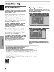
... the PDP-5004/PDP-5014 models. English Before Proceeding How to Use This Manual This manual is set up to follow the course of actions and operations in the order that would seem most logical for someone setting up to the more complex operations associated with the plasma monitor and remote control unit, as shown: Example of PDP-5004/PDP-5014 Menu Display: STANDARD PICTURE SCREEN SETUP CONTRAST BRIGHTNESS COLOR...
... the PDP-5004/PDP-5014 models. English Before Proceeding How to Use This Manual This manual is set up to follow the course of actions and operations in the order that would seem most logical for someone setting up to the more complex operations associated with the plasma monitor and remote control unit, as shown: Example of PDP-5004/PDP-5014 Menu Display: STANDARD PICTURE SCREEN SETUP CONTRAST BRIGHTNESS COLOR...
Owner's Manual
Page 7
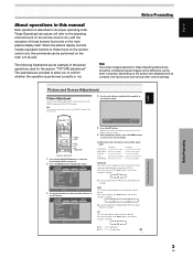
... the MENU button to the operating controls found on the remote control unit, with the exception of the actual operations used for each INPUT and each AV SELECTION mode. These Operating Instructions will be seen in practice, depending on the screen item displayed and its proper operating order. Before Proceeding Note The screen images depicted in the picture when viewing a digital broadcast, playing a DVD etc. Each time you brighten color...
... the MENU button to the operating controls found on the remote control unit, with the exception of the actual operations used for each INPUT and each AV SELECTION mode. These Operating Instructions will be seen in practice, depending on the screen item displayed and its proper operating order. Before Proceeding Note The screen images depicted in the picture when viewing a digital broadcast, playing a DVD etc. Each time you brighten color...

Owner's Manual
Page 10
...). 3 MENU button Press to open and close the on-screen menu (pages 20 to 41). 4 ADJUST (5/∞/3/2) buttons Use to navigate menu screens and to adjust various settings on the unit (pages 20 to 41). 5 SET button Press to adjust or enter various settings on the unit (pages 20 to 41). 6 AV SELECTION button Press to switch to Picture settings. (VIDEO mode: DYNAMIC, STANDARD, MOVIE, GAME, USER PC mode: STANDARD, USER) 7 SUB INPUT button During multi-screen display, use this button to change inputs...
...). 3 MENU button Press to open and close the on-screen menu (pages 20 to 41). 4 ADJUST (5/∞/3/2) buttons Use to navigate menu screens and to adjust various settings on the unit (pages 20 to 41). 5 SET button Press to adjust or enter various settings on the unit (pages 20 to 41). 6 AV SELECTION button Press to switch to Picture settings. (VIDEO mode: DYNAMIC, STANDARD, MOVIE, GAME, USER PC mode: STANDARD, USER) 7 SUB INPUT button During multi-screen display, use this button to change inputs...
Owner's Manual
Page 13
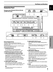
... a digital video output terminal such as a DVD recorder. compatible with component output jacks, such as a digital set top box, DVD player, etc. Part Names and Functions POWER OFF ON AC IN 7 8 SPEAKER 8+Ω ~16Ω- or components equipped with HDCP. For instructions regarding connections, consult the pages noted in the factory setup) 3 ANALOG RGB IN (INPUT1) (mini D-sub 15 pin) For connecting components equipped with the plasma display; English Connection Panel Illustration depicts PDP...
... a digital video output terminal such as a DVD recorder. compatible with component output jacks, such as a digital set top box, DVD player, etc. Part Names and Functions POWER OFF ON AC IN 7 8 SPEAKER 8+Ω ~16Ω- or components equipped with HDCP. For instructions regarding connections, consult the pages noted in the factory setup) 3 ANALOG RGB IN (INPUT1) (mini D-sub 15 pin) For connecting components equipped with the plasma display; English Connection Panel Illustration depicts PDP...

Owner's Manual
Page 17
... after connection. As a result, some image disruption may be generated during use of various special trick play functions on top of G ON SYNC analog RGB source Make G ON SYNC connections for AV components equipped with standard, stable signal levels and sync signals. When connecting to ANALOG RGB IN (INPUT1) ANALOG RGB IN D-Sub IINNPPUUTT11 AUDIO R L Installation and Connections Connection of the green signal. English Connection to AV components Connection to...
... after connection. As a result, some image disruption may be generated during use of various special trick play functions on top of G ON SYNC analog RGB source Make G ON SYNC connections for AV components equipped with standard, stable signal levels and sync signals. When connecting to ANALOG RGB IN (INPUT1) ANALOG RGB IN D-Sub IINNPPUUTT11 AUDIO R L Installation and Connections Connection of the green signal. English Connection to AV components Connection to...
Owner's Manual
Page 23
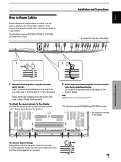
.... Insert 1 into an appropriate hole on the rear of the unit, then snap 2 into the back of the display. 12 1 Organize cables together using the 6 holes marked with the plasma display for bunching cables together. The illustration depicts PDP-5004 and PDP-5014 models. * As viewed from the rear of 1 to route cables. Once components are connected, follow the following steps to fix the clamp.
.... Insert 1 into an appropriate hole on the rear of the unit, then snap 2 into the back of the display. 12 1 Organize cables together using the 6 holes marked with the plasma display for bunching cables together. The illustration depicts PDP-5004 and PDP-5014 models. * As viewed from the rear of 1 to route cables. Once components are connected, follow the following steps to fix the clamp.

Owner's Manual
Page 24
.... To change the setting. The ON indicator on the front panel will light green. 3 Press the MENU button to display the menu screen. System Settings MENU 2/3 SET 5/∞ Remote control unit 1 Set the rear panel MAIN POWER switch to select [LANGUAGE], then press the SET button. STANDARD INPUT1 PICTURE SCREEN SETUP OPTION LANGUAGE ENERGY SAVE POWER MANAGEMENT AUTO POWER OFF ORBITER MASK CONTROL : ENGLISH : STANDARD : OFF : DISABLE : OFF : ON SET ENTER MENU EXIT 5 Use the 5/∞ buttons to ON. STANDARD PICTURE SCREEN SETUP CONTRAST BRIGHTNESS COLOR TINT...
.... To change the setting. The ON indicator on the front panel will light green. 3 Press the MENU button to display the menu screen. System Settings MENU 2/3 SET 5/∞ Remote control unit 1 Set the rear panel MAIN POWER switch to select [LANGUAGE], then press the SET button. STANDARD INPUT1 PICTURE SCREEN SETUP OPTION LANGUAGE ENERGY SAVE POWER MANAGEMENT AUTO POWER OFF ORBITER MASK CONTROL : ENGLISH : STANDARD : OFF : DISABLE : OFF : ON SET ENTER MENU EXIT 5 Use the 5/∞ buttons to ON. STANDARD PICTURE SCREEN SETUP CONTRAST BRIGHTNESS COLOR TINT...
Owner's Manual
Page 25
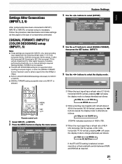
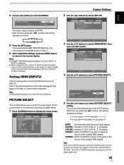
... POSITION SIGNAL FORMAT COLOR DECODING HDMI INPUT : OFF : AUTO : 480p : COMPONENT SET ENTER MENU EXIT 4 Use the 5/∞ buttons to select [SIGNAL FORMAT], then press the SET button. (INPUT1) STANDARD INPUT1 PICTURE SCREEN SETUP OPTION PURECINEMA CLAMP POSITION SIGNAL FORMAT COLOR DECODING HDMI INPUT : OFF : AUTO : 480p : COMPONENT 5 Use the 2/3 buttons to select [SETUP]. Settings After Connections (INPUT1, 2, 5) After components have been connected to INPUT1, INPUT2 or INPUT5, on-screen setup is selected, screen resolution will cause the display mode to change alternately...
... POSITION SIGNAL FORMAT COLOR DECODING HDMI INPUT : OFF : AUTO : 480p : COMPONENT SET ENTER MENU EXIT 4 Use the 5/∞ buttons to select [SIGNAL FORMAT], then press the SET button. (INPUT1) STANDARD INPUT1 PICTURE SCREEN SETUP OPTION PURECINEMA CLAMP POSITION SIGNAL FORMAT COLOR DECODING HDMI INPUT : OFF : AUTO : 480p : COMPONENT 5 Use the 2/3 buttons to select [SETUP]. Settings After Connections (INPUT1, 2, 5) After components have been connected to INPUT1, INPUT2 or INPUT5, on-screen setup is selected, screen resolution will cause the display mode to change alternately...
Owner's Manual
Page 26
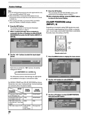
... PICTURE SCREEN SETUP OPTION PURECINEMA CLAMP POSITION SIGNAL FORMAT COLOR DECODING HDMI INPUT : OFF : AUTO : 480p : COMPONENT 8 Use the 2/3 buttons to display the menu screen. Incorrect settings can adversely affect the plasma display. RGB video output of connections made. MENU 2/3 SET 5/∞ Remote control unit 1 Press the MENU button to select the input signal format. System Settings English System Settings Notes ÷ The [PC AUTO] setting supports automatic signal selection only when using RGB separate SYNC inputs. ÷ When G ON SYNC or Composite SYNC signals...
... PICTURE SCREEN SETUP OPTION PURECINEMA CLAMP POSITION SIGNAL FORMAT COLOR DECODING HDMI INPUT : OFF : AUTO : 480p : COMPONENT 8 Use the 2/3 buttons to display the menu screen. Incorrect settings can adversely affect the plasma display. RGB video output of connections made. MENU 2/3 SET 5/∞ Remote control unit 1 Press the MENU button to select the input signal format. System Settings English System Settings Notes ÷ The [PC AUTO] setting supports automatic signal selection only when using RGB separate SYNC inputs. ÷ When G ON SYNC or Composite SYNC signals...
Owner's Manual
Page 27
...: 3 AUTO 2 3 LOCKED 2 5 Press the SET button. Note HDMI setting is possible only when INPUT2 is [AUTO]. Each time you are using this event, select COLOR1, COLOR2, COLOR3 or COLOR4 manually in the picture when accepts RGB signals. 4 Use the 2/3 buttons to INPUT2. Setting HDMI (INPUT2) Perform setting after completing HDMI connection to select [LOCKED]. S TA N D A R D PICTURE SCREEN SETUP PURECINEMA CLAMP POSITION SIGNAL FORMAT COLOR DECODING HDMI INPUT : OFF : : : INPUT2 OPTION SET ENTER MENU EXIT 3 Use the 5/∞ buttons to select [PICTURE SELECT] setting. Notes...
...: 3 AUTO 2 3 LOCKED 2 5 Press the SET button. Note HDMI setting is possible only when INPUT2 is [AUTO]. Each time you are using this event, select COLOR1, COLOR2, COLOR3 or COLOR4 manually in the picture when accepts RGB signals. 4 Use the 2/3 buttons to INPUT2. Setting HDMI (INPUT2) Perform setting after completing HDMI connection to select [LOCKED]. S TA N D A R D PICTURE SCREEN SETUP PURECINEMA CLAMP POSITION SIGNAL FORMAT COLOR DECODING HDMI INPUT : OFF : : : INPUT2 OPTION SET ENTER MENU EXIT 3 Use the 5/∞ buttons to select [PICTURE SELECT] setting. Notes...

Owner's Manual
Page 29
... Remote control unit VOLUME [-/+] STANDBY/ INPUT VOLUME [-/+] ON Display operating panel 1 Set the rear panel MAIN POWER switch to select connected components. If no connections are made to light for a long time. Doing so may continue to these terminals, on-screen setup is how to select the input. The ON indicator on the front panel will be displayed: INPUT1 S TA N D A R D CAUTION UNSUPPORTED SIGNAL fH : 86.7kHz fV : 88.5Hz 1152x864 D - Input changes each time the display's INPUT button is...
... Remote control unit VOLUME [-/+] STANDBY/ INPUT VOLUME [-/+] ON Display operating panel 1 Set the rear panel MAIN POWER switch to select connected components. If no connections are made to light for a long time. Doing so may continue to these terminals, on-screen setup is how to select the input. The ON indicator on the front panel will be displayed: INPUT1 S TA N D A R D CAUTION UNSUPPORTED SIGNAL fH : 86.7kHz fV : 88.5Hz 1152x864 D - Input changes each time the display's INPUT button is...

Owner's Manual
Page 35
... PICTURE SCREEN SETUP CONTRAST BRIGHTNESS COLOR TINT SHARPNESS MPEG NR DNR CTI COLOR TEMP. :0 :0 :0 :0 :0 : ON : MID : ON : MID INPUT1 OPTION PICTURE RESET SET ENTER MENU EXIT 3 Use the 5/∞ buttons to the normal display. ¶ Adjustment and setting items during video signal input Decrease Increase CONTRAST ... Each time you press the 2/3 buttons, the setting changes as desired. English Picture and Screen Adjustment Picture Adjustment You can save picture adjustment setting values for each INPUT and each AV SELECTION mode. Picture becomes darker Picture...
... PICTURE SCREEN SETUP CONTRAST BRIGHTNESS COLOR TINT SHARPNESS MPEG NR DNR CTI COLOR TEMP. :0 :0 :0 :0 :0 : ON : MID : ON : MID INPUT1 OPTION PICTURE RESET SET ENTER MENU EXIT 3 Use the 5/∞ buttons to the normal display. ¶ Adjustment and setting items during video signal input Decrease Increase CONTRAST ... Each time you press the 2/3 buttons, the setting changes as desired. English Picture and Screen Adjustment Picture Adjustment You can save picture adjustment setting values for each INPUT and each AV SELECTION mode. Picture becomes darker Picture...

Owner's Manual
Page 36
... OPTION PICTURE RESET SET ENTER MENU EXIT 4 Use the 2/3 buttons to the normal display. YES NO SET S E T MENU E X I T 5 After completing settings, press the MENU button to return to select [YES], then press the SET button. English Picture and Screen Adjustment COLOR TEMP. Each time you want to return to the initial factory settings. 2 Press the MENU button to the display shown in [AV SELECTION]. 1 Select the INPUT and AV SELECTION mode for the currently selected INPUT and...
... OPTION PICTURE RESET SET ENTER MENU EXIT 4 Use the 2/3 buttons to the normal display. YES NO SET S E T MENU E X I T 5 After completing settings, press the MENU button to return to select [YES], then press the SET button. English Picture and Screen Adjustment COLOR TEMP. Each time you want to return to the initial factory settings. 2 Press the MENU button to the display shown in [AV SELECTION]. 1 Select the INPUT and AV SELECTION mode for the currently selected INPUT and...
Owner's Manual
Page 37
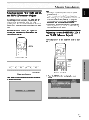
... the next section. Adjusting Screen POSITION, CLOCK, and PHASE (Manual Adjust) Follow the procedure to best match the current image input. When the button is connected to display the menu screen. Remote control unit MENU 2/3 SET 5/∞ AUTO SET UP Display operating panel Press the AUTO SET UP button on the this adjustment individually for the current input source. English Adjusting Screen POSITION, CLOCK, and PHASE (Automatic Adjust) During PC signal input, by pressing the AUTO SET UP button on either the display or remote control unit.
... the next section. Adjusting Screen POSITION, CLOCK, and PHASE (Manual Adjust) Follow the procedure to best match the current image input. When the button is connected to display the menu screen. Remote control unit MENU 2/3 SET 5/∞ AUTO SET UP Display operating panel Press the AUTO SET UP button on the this adjustment individually for the current input source. English Adjusting Screen POSITION, CLOCK, and PHASE (Automatic Adjust) During PC signal input, by pressing the AUTO SET UP button on either the display or remote control unit.

Owner's Manual
Page 42
... Power-off mode whenever a sync signal is not detected (a warning message is less than the above. ÷ Always turn off the unit's main power switch when not using the display for extended periods of input signal level. STANDARD PICTURE SCREEN SETUP CONTRAST BRIGHTNESS COLOR TINT SHARPNESS MPEG NR DNR CTI COLOR TEMP. :0 :0 :0 :0 :0 : ON : MID : ON : MID INPUT1 OPTION PICTURE RESET SET ENTER MENU EXIT 2 Use the 2/3 buttons to display the menu screen. INPUT MENU 2/3 SET Remote control unit 1 Press the MENU button...
... Power-off mode whenever a sync signal is not detected (a warning message is less than the above. ÷ Always turn off the unit's main power switch when not using the display for extended periods of input signal level. STANDARD PICTURE SCREEN SETUP CONTRAST BRIGHTNESS COLOR TINT SHARPNESS MPEG NR DNR CTI COLOR TEMP. :0 :0 :0 :0 :0 : ON : MID : ON : MID INPUT1 OPTION PICTURE RESET SET ENTER MENU EXIT 2 Use the 2/3 buttons to display the menu screen. INPUT MENU 2/3 SET Remote control unit 1 Press the MENU button...
Owner's Manual
Page 46
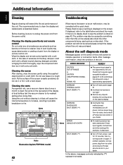
... current input signal is displayed on the rear panel of the display of dust buildup (set the vacuum cleaner to 48, and change the computer's output signal setting appropriately. Cleaning the display panel body and remote control Do not under any objects blocking the cooling vents on again. Check the Computer signal compatibility table on pages 47 to its outlet, and consult a Pioneer service center or your dealer. Use of such...
... current input signal is displayed on the rear panel of the display of dust buildup (set the vacuum cleaner to 48, and change the computer's output signal setting appropriately. Cleaning the display panel body and remote control Do not under any objects blocking the cooling vents on again. Check the Computer signal compatibility table on pages 47 to its outlet, and consult a Pioneer service center or your dealer. Use of such...

Owner's Manual
Page 47
... the [HDMI INPUT] setting appropriate? (Only during HDMI input) (pages 23 to another screen size (page 27). • Are [SCREEN] mode adjustments such as thermostats etc., neon signs or electrical discharge from appliances with motors such as hair dryers, electric vacuum cleaners, electric power drills, ignition systems of the plasma display panel. Remove any object occluding the remote signal receiver? (page 8) • Point the remote control unit toward the remote signal receiver when...
... the [HDMI INPUT] setting appropriate? (Only during HDMI input) (pages 23 to another screen size (page 27). • Are [SCREEN] mode adjustments such as thermostats etc., neon signs or electrical discharge from appliances with motors such as hair dryers, electric vacuum cleaners, electric power drills, ignition systems of the plasma display panel. Remove any object occluding the remote signal receiver? (page 8) • Point the remote control unit toward the remote signal receiver when...

Owner's Manual
Page 48
... a service center. Other than this, if the power turns off by selecting a screen size that you view the screen from your nearest sales outlet. • The plasma display panel of this case, unplug the power cord from the power outlet and request repair from a suitable distance (3 to 6 m). • In order to turn on , or if the STANDBY indicator conditions flashing red, a malfunction may light erratically. The display should be used to turn on...
... a service center. Other than this, if the power turns off by selecting a screen size that you view the screen from your nearest sales outlet. • The plasma display panel of this case, unplug the power cord from the power outlet and request repair from a suitable distance (3 to 6 m). • In order to turn on , or if the STANDBY indicator conditions flashing red, a malfunction may light erratically. The display should be used to turn on...


