Owner's Manual
Page 2
... start Information to User 3 After-sales service for Pioneer products 3 Visit our website 3 Before connecting/installing the amplifier 4 Setting the Unit What's what 5 Setting gain properly 5 Connecting the units Connection diagram 7 Before connecting the amplifier 7 About bridged mode 8 About suitable specification of speaker...when using the RCA input jack 10 Connections when using the speaker input wire 10 Connecting the power terminal 11 Connecting the speaker output terminals 12 Installation Before installing the amplifier 13 Example of installation on the floor mat or chassis 13 Additional ...
... start Information to User 3 After-sales service for Pioneer products 3 Visit our website 3 Before connecting/installing the amplifier 4 Setting the Unit What's what 5 Setting gain properly 5 Connecting the units Connection diagram 7 Before connecting the amplifier 7 About bridged mode 8 About suitable specification of speaker...when using the RCA input jack 10 Connections when using the speaker input wire 10 Connecting the power terminal 11 Connecting the speaker output terminals 12 Installation Before installing the amplifier 13 Example of installation on the floor mat or chassis 13 Additional ...
Owner's Manual
Page 4
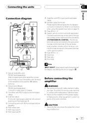
... to avoid the risk of the amplifier and any abnormality, the power supply to the amplifier is at rest or idling may also heat up and cause minor burns. ! Connect the battery wire directly to the car battery positive terminal + and the ground wire to come into contact with a...Handling the cord on this number on the bottom of a special red battery and ground wire RD-223, available separately, is for vehicles with liquids. sociated with accessories sold battery wire or the amplifier fuse blows. Before installing in overheating and smoke, damage to cause cancer and birth defects...
... to avoid the risk of the amplifier and any abnormality, the power supply to the amplifier is at rest or idling may also heat up and cause minor burns. ! Connect the battery wire directly to the car battery positive terminal + and the ground wire to come into contact with a...Handling the cord on this number on the bottom of a special red battery and ground wire RD-223, available separately, is for vehicles with liquids. sociated with accessories sold battery wire or the amplifier fuse blows. Before installing in overheating and smoke, damage to cause cancer and birth defects...
Owner's Manual
Page 7
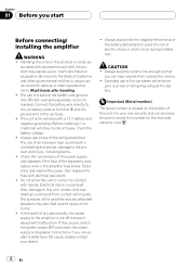
... tape. ! Never cut the insulation of the power supply to feed power to other amplifier connections, finally connect the battery wire terminal of the amplifier to the positive (+) battery terminal. 2 Ground wire (Black) RD-223 (sold separately) Connect to metal body or chassis. 3 Car stereo... After completing all other equipment. En 7 Connecting the units Section 03 English Connection diagram 9 Amplifier with RCA input jacks (sold separately) Connect male terminal of this wire to the system remote control terminal of the car stereo (SYSTEM REMOTE CONTROL). Refer to the ...
... tape. ! Never cut the insulation of the power supply to feed power to other amplifier connections, finally connect the battery wire terminal of the amplifier to the positive (+) battery terminal. 2 Ground wire (Black) RD-223 (sold separately) Connect to metal body or chassis. 3 Car stereo... After completing all other equipment. En 7 Connecting the units Section 03 English Connection diagram 9 Amplifier with RCA input jacks (sold separately) Connect male terminal of this wire to the system remote control terminal of the car stereo (SYSTEM REMOTE CONTROL). Refer to the ...
Owner's Manual
Page 8
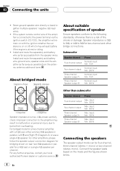
...Left + and Right * (Diagram A) or use a single 4 W speaker. Install and route the separately sold battery wire, ground wire, speaker wires and the amplifier as far away as possible from the antenna, antenna cable and tuner. Improper connection to the following standards, otherwise there ... wire directly or band together multiple speakers' negative (*) lead wires. ! Install and route the separately sold battery wire as far as possible from the speaker wires. input: Min. 120 W Three-channel Speaker output B Max. For any further enquiries, contact your local authorized Pioneer dealer...
...Left + and Right * (Diagram A) or use a single 4 W speaker. Install and route the separately sold battery wire, ground wire, speaker wires and the amplifier as far away as possible from the antenna, antenna cable and tuner. Improper connection to the following standards, otherwise there ... wire directly or band together multiple speakers' negative (*) lead wires. ! Install and route the separately sold battery wire as far as possible from the speaker wires. input: Min. 120 W Three-channel Speaker output B Max. For any further enquiries, contact your local authorized Pioneer dealer...
Owner's Manual
Page 10
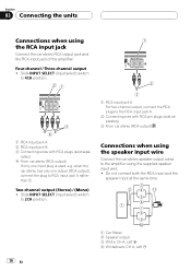
... output (Stereo) / (Mono) ! when the car stereo has only one input plug is used, e.g. Connections when using the speaker input wire Connect the car stereo speaker output wires to the RCA input jack A. 2 Connecting wire with RCA pin plugs (sold separately) 3 From car stereo (RCA output) 1 RCA input jack A 2 RCA input jack B 3 Connecting...jack A rather than B. Slide INPUT SELECT (input select) switch to 4CH position. 1 RCA input jack A For two-channel output, connect the RCA plugs to the amplifier using the RCA input jack Connect the car stereo RCA output jack and the RCA input jack of the...
... output (Stereo) / (Mono) ! when the car stereo has only one input plug is used, e.g. Connections when using the speaker input wire Connect the car stereo speaker output wires to the RCA input jack A. 2 Connecting wire with RCA pin plugs (sold separately) 3 From car stereo (RCA output) 1 RCA input jack A 2 RCA input jack B 3 Connecting...jack A rather than B. Slide INPUT SELECT (input select) switch to 4CH position. 1 RCA input jack A For two-channel output, connect the RCA plugs to the amplifier using the RCA input jack Connect the car stereo RCA output jack and the RCA input jack of the...
Owner's Manual
Page 11
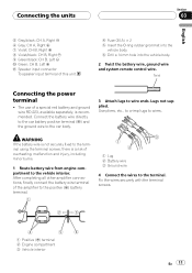
... the car body. 3 Attach lugs to the terminal. After completing all other amplifier connections, finally connect the battery wire terminal of the amplifier to the positive (+) battery terminal. 1 Lug 2 Battery wire 3 Ground wire 4 Connect the wires to wire ends. WARNING If the battery wire is not securely fixed to the terminal using the terminal screws, there is recommended...
... the car body. 3 Attach lugs to the terminal. After completing all other amplifier connections, finally connect the battery wire terminal of the amplifier to the positive (+) battery terminal. 1 Lug 2 Battery wire 3 Ground wire 4 Connect the wires to wire ends. WARNING If the battery wire is not securely fixed to the terminal using the terminal screws, there is recommended...
Owner's Manual
Page 12
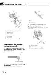
... 03 Connecting the units 1 System remote control terminal 2 GND terminal 3 Power terminal 4 Terminal screws 5 Battery wire 6 Ground wire 7 System remote control wire 1 Lug 2 Speaker wire 3 Connect the speaker wires to wires. 12 En Twist 1 Terminal screws 2 Speaker wires 3 Speaker output terminals 2 Attach lugs to speaker wire ends. Connecting the speaker output terminals 1 Expose the end of the speaker...
... 03 Connecting the units 1 System remote control terminal 2 GND terminal 3 Power terminal 4 Terminal screws 5 Battery wire 6 Ground wire 7 System remote control wire 1 Lug 2 Speaker wire 3 Connect the speaker wires to wires. 12 En Twist 1 Terminal screws 2 Speaker wires 3 Speaker output terminals 2 Attach lugs to speaker wire ends. Connecting the speaker output terminals 1 Expose the end of the speaker...
Owner's Manual
Page 13
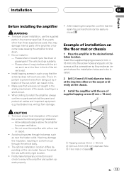
... tire, jack and tools can result in : - Make sure that wires are to shut down. ! When drilling to install the amplifier, always confirm no parts are used, they make temporary connections and check to prevent wires from damage. ! To ensure proper heat dissipation of installation on the ...damage internal parts of supplied tapping screws (4 mm × 18 mm). Example of the ampli- Do not install in fire. ! If any wire. This is important to ensure the amplifier and system operate properly. 1 Tapping-screws (4 mm × 18 mm) 2 Drill a 2.5 mm (1/8 inch) diameter hole 3 Floor ...
... tire, jack and tools can result in : - Make sure that wires are to shut down. ! When drilling to install the amplifier, always confirm no parts are used, they make temporary connections and check to prevent wires from damage. ! To ensure proper heat dissipation of installation on the ...damage internal parts of supplied tapping screws (4 mm × 18 mm). Example of the ampli- Do not install in fire. ! If any wire. This is important to ensure the amplifier and system operate properly. 1 Tapping-screws (4 mm × 18 mm) 2 Drill a 2.5 mm (1/8 inch) diameter hole 3 Floor ...
Owner's Manual
Page 14
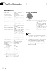
...value when working out total current drawn by this unit when an audio signal is nearly the maximum current drawn by multiple power amplifiers. 14 En Appendix Additional information Specifications Power source 14.4 V DC (10.8 V to 15.1 V allowable) Grounding system Negative ...; 2 Dimensions (W × H × D) ... 265 mm × 62 mm × 346 mm (10-3/8 in. ×2-1/2 in. × 1 ft. 2 in.) Weight 3.8 kg (Leads for wiring not included) Maximum power output ....... 120 W × 4 (4 W) / 300 W × 2 (4 W) Continuous power output ... 60 W × 4 (at 14.4 V, 4 W, 20 Hz to 20...
...value when working out total current drawn by this unit when an audio signal is nearly the maximum current drawn by multiple power amplifiers. 14 En Appendix Additional information Specifications Power source 14.4 V DC (10.8 V to 15.1 V allowable) Grounding system Negative ...; 2 Dimensions (W × H × D) ... 265 mm × 62 mm × 346 mm (10-3/8 in. ×2-1/2 in. × 1 ft. 2 in.) Weight 3.8 kg (Leads for wiring not included) Maximum power output ....... 120 W × 4 (4 W) / 300 W × 2 (4 W) Continuous power output ... 60 W × 4 (at 14.4 V, 4 W, 20 Hz to 20...


