Owner's Manual
Page 2
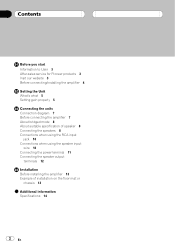
... Information to User 3 After-sales service for Pioneer products 3 Visit our website 3 Before connecting/installing the amplifier 4 Setting the Unit What's what 5 Setting gain properly 5 Connecting the units Connection diagram 7 Before connecting the amplifier 7 About bridged mode 8 About suitable specification of speaker 8 Connecting the speakers 8 Connections when using the RCA input jack 10 Connections when using the speaker input wire 10 Connecting the power terminal 11 Connecting the speaker output terminals 12 Installation Before installing the amplifier 13 Example of installation on the...
... Information to User 3 After-sales service for Pioneer products 3 Visit our website 3 Before connecting/installing the amplifier 4 Setting the Unit What's what 5 Setting gain properly 5 Connecting the units Connection diagram 7 Before connecting the amplifier 7 About bridged mode 8 About suitable specification of speaker 8 Connecting the speakers 8 Connections when using the RCA input jack 10 Connections when using the speaker input wire 10 Connecting the power terminal 11 Connecting the speaker output terminals 12 Installation Before installing the amplifier 13 Example of installation on the...
Owner's Manual
Page 3
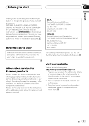
... PIONEER product. After-sales service for Pioneer products Please contact the dealer or distributor from where you purchased this unit for purchasing this manual before attempting operation. Pioneer Electronics (USA) Inc. Before you start Section 01 English Thank you for after-sales service (including warranty conditions) or any questions, contact your nearest Pioneer authorized dealer or installation specialist. Please read all instructions...
... PIONEER product. After-sales service for Pioneer products Please contact the dealer or distributor from where you purchased this unit for purchasing this manual before attempting operation. Pioneer Electronics (USA) Inc. Before you start Section 01 English Thank you for after-sales service (including warranty conditions) or any questions, contact your nearest Pioneer authorized dealer or installation specialist. Please read all instructions...
Owner's Manual
Page 4
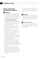
... the car battery positive terminal + and the ground wire to the amplifier is for vehicles with accessories sold battery wire or the amplifier fuse blows. Always use of this unit. Determine and resolve the cause, then replace the fuse with liquids. Always disconnect the negative * terminal of the battery beforehand to avoid the risk of the separately sold with liquids. The use a fuse of the amplifier and any abnormality, the power...
... the car battery positive terminal + and the ground wire to the amplifier is for vehicles with accessories sold battery wire or the amplifier fuse blows. Always use of this unit. Determine and resolve the cause, then replace the fuse with liquids. Always disconnect the negative * terminal of the battery beforehand to avoid the risk of the separately sold with liquids. The use a fuse of the amplifier and any abnormality, the power...
Owner's Manual
Page 5
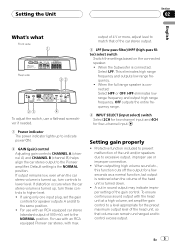
... sound output with the head unit at a high volume, set to lower level. For use with max. Setting gain properly ! Default setting is connected: Select LPF. When the full range speaker is turned up, turn controls to the NORMAL position. Setting the Unit Section 02 English What's what Front side Rear side To adjust the switch, use a flathead screwdriver if needed. 1 Power indicator The power indicator lights up to indicate power ON. 2 GAIN (gain) control Adjusting gain controls CHANNEL A (channel A) and CHANNEL B (channel B) helps align the car stereo output to higher level...
... sound output with the head unit at a high volume, set to lower level. For use with max. Setting gain properly ! Default setting is connected: Select LPF. When the full range speaker is turned up, turn controls to the NORMAL position. Setting the Unit Section 02 English What's what Front side Rear side To adjust the switch, use a flathead screwdriver if needed. 1 Power indicator The power indicator lights up to indicate power ON. 2 GAIN (gain) control Adjusting gain controls CHANNEL A (channel A) and CHANNEL B (channel B) helps align the car stereo output to higher level...
Owner's Manual
Page 6
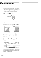
... Pioneer Service Station. Relationship between amplifier gain and head unit output power If amplifier gain is raised improperly, this will simply increase distortion, with high output, if you raise the gain of this unit Preout level: 2 V (Standard: 500mV) Above illustration shows NORMAL gain setting. Gain control of the amplifier the power changes only slightly. 6 En Signal waveform when outputting at high volume using amplifier gain control Signal waveform distorted with little increase in power. Despite correct volume and gain settings, the unit sound still cuts...
... Pioneer Service Station. Relationship between amplifier gain and head unit output power If amplifier gain is raised improperly, this will simply increase distortion, with high output, if you raise the gain of this unit Preout level: 2 V (Standard: 500mV) Above illustration shows NORMAL gain setting. Gain control of the amplifier the power changes only slightly. 6 En Signal waveform when outputting at high volume using amplifier gain control Signal waveform distorted with little increase in power. Despite correct volume and gain settings, the unit sound still cuts...
Owner's Manual
Page 7
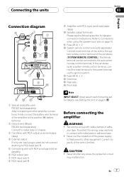
... positive (+) battery terminal. 2 Ground wire (Black) RD-223 (sold separately) Connect to metal body or chassis. 3 Car stereo with RCA output jacks (sold separately) 6 RCA output jack 7 RCA input jack A 8 RCA input jack B Note INPUT SELECT (input select) switch must be connected to Connections when using the speaker input wire on page 5. En 7 Refer to the auto-antenna relay control terminal. To protect the wiring, wrap sections in adhesive tape. ! b Fuse (25 A) × 2 c System remote control wire (sold separately) a Speaker output terminals Please see Setting the Unit on...
... positive (+) battery terminal. 2 Ground wire (Black) RD-223 (sold separately) Connect to metal body or chassis. 3 Car stereo with RCA output jacks (sold separately) 6 RCA output jack 7 RCA input jack A 8 RCA input jack B Note INPUT SELECT (input select) switch must be connected to Connections when using the speaker input wire on page 5. En 7 Refer to the auto-antenna relay control terminal. To protect the wiring, wrap sections in adhesive tape. ! b Fuse (25 A) × 2 c System remote control wire (sold separately) a Speaker output terminals Please see Setting the Unit on...
Owner's Manual
Page 8
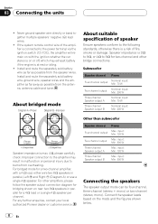
...-channel Speaker output A Nominal input: Min. 70 W Three-channel Speaker output B Nominal input: Min. 200 W Speaker impedance is 2 W to 8 W, or 4 W to burns from overheating. Other than subwoofer Speaker channel Power Four-channel output Max. input: Min. 120 W Three-channel Speaker output B Max. For other bridge connections. For any further enquiries, contact your local authorized Pioneer dealer or customer service. Section 03 Connecting the units ! If the system remote control wire of fire, smoke or damage. About bridged mode About suitable specification of speaker...
...-channel Speaker output A Nominal input: Min. 70 W Three-channel Speaker output B Nominal input: Min. 200 W Speaker impedance is 2 W to 8 W, or 4 W to burns from overheating. Other than subwoofer Speaker channel Power Four-channel output Max. input: Min. 120 W Three-channel Speaker output B Max. For other bridge connections. For any further enquiries, contact your local authorized Pioneer dealer or customer service. Section 03 Connecting the units ! If the system remote control wire of fire, smoke or damage. About bridged mode About suitable specification of speaker...
Owner's Manual
Page 9
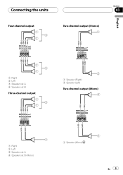
Connecting the units Four-channel output Section 03 Two-channel output (Stereo) English 1 Right 2 Left 3 Speaker out A 4 Speaker out B Three-channel output 1 Speaker (Right) 2 Speaker (Left) Two-channel output (Mono) 1 Right 2 Left 3 Speaker out A 4 Speaker out B (Mono) 1 Speaker (Mono) En 9
Connecting the units Four-channel output Section 03 Two-channel output (Stereo) English 1 Right 2 Left 3 Speaker out A 4 Speaker out B Three-channel output 1 Speaker (Right) 2 Speaker (Left) Two-channel output (Mono) 1 Right 2 Left 3 Speaker out A 4 Speaker out B (Mono) 1 Speaker (Mono) En 9
Owner's Manual
Page 10
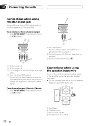
...black: CH A, Left * Four-channel / Three-channel output ! Slide INPUT SELECT (input select) switch to the RCA input jack A. 2 Connecting wire with RCA pin plugs (sold separately) 3 From car stereo (RCA output) 1 RCA input jack A 2 RCA input jack B 3 Connecting wires with RCA plugs (sold sepa- Connections when using the speaker input wire Connect the car stereo speaker output wires to RCA input jack A rather than B. rately) 4 From car stereo (RCA output) If only one output (RCA output), connect the plug to the amplifier using the RCA input jack Connect the car stereo RCA output...
...black: CH A, Left * Four-channel / Three-channel output ! Slide INPUT SELECT (input select) switch to the RCA input jack A. 2 Connecting wire with RCA pin plugs (sold separately) 3 From car stereo (RCA output) 1 RCA input jack A 2 RCA input jack B 3 Connecting wires with RCA plugs (sold sepa- Connections when using the speaker input wire Connect the car stereo speaker output wires to RCA input jack A rather than B. rately) 4 From car stereo (RCA output) If only one output (RCA output), connect the plug to the amplifier using the RCA input jack Connect the car stereo RCA output...
Owner's Manual
Page 11
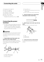
... + b Speaker input connector To speaker input terminal of overheating, malfunction and injury, including minor burns. 1 Route battery wire from engine compartment to wires. The use of a special red battery and ground wire RD-223, available separately, is a risk of this unit. 4 Fuse (30 A) × 2 5 Insert the O-ring rubber grommet into the vehicle body. 6 Drill a 14 mm hole into the vehicle body. 2 Twist the battery wire, ground wire and system remote control wire. Connect the battery wire directly...
... + b Speaker input connector To speaker input terminal of overheating, malfunction and injury, including minor burns. 1 Route battery wire from engine compartment to wires. The use of a special red battery and ground wire RD-223, available separately, is a risk of this unit. 4 Fuse (30 A) × 2 5 Insert the O-ring rubber grommet into the vehicle body. 6 Drill a 14 mm hole into the vehicle body. 2 Twist the battery wire, ground wire and system remote control wire. Connect the battery wire directly...
Owner's Manual
Page 12
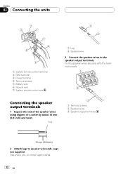
Connecting the speaker output terminals 1 Expose the end of the speaker wires using nippers or a cutter by about 10 mm (3/8 inch) and twist. Fix the speaker wires securely with the terminal screws. Use pliers, etc., to crimp lugs to the speaker output terminals. Lugs not supplied. Section 03 Connecting the units 1 System remote control terminal 2 GND terminal 3 Power terminal 4 Terminal screws 5 Battery wire 6 Ground wire 7 System remote control wire 1 Lug 2 Speaker wire 3 Connect the speaker wires to wires. 12 En Twist 1 Terminal screws 2 Speaker wires 3 Speaker output ...
Connecting the speaker output terminals 1 Expose the end of the speaker wires using nippers or a cutter by about 10 mm (3/8 inch) and twist. Fix the speaker wires securely with the terminal screws. Use pliers, etc., to crimp lugs to the speaker output terminals. Lugs not supplied. Section 03 Connecting the units 1 System remote control terminal 2 GND terminal 3 Power terminal 4 Terminal screws 5 Battery wire 6 Ground wire 7 System remote control wire 1 Lug 2 Speaker wire 3 Connect the speaker wires to wires. 12 En Twist 1 Terminal screws 2 Speaker wires 3 Speaker output ...
Owner's Manual
Page 13
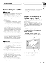
... damage internal parts of the car, which can be located. 2 Drill 2.5 mm (1/8 inch) diameter holes at a sufficiently rigid location. ! Do not install in a short-circuit. ! Make sure that the spare tire, jack and tools can result in the sliding mechanism of the driver's seat. ! After installing the amplifier, confirm that wires are behind the panel and protect all cables and important...
... damage internal parts of the car, which can be located. 2 Drill 2.5 mm (1/8 inch) diameter holes at a sufficiently rigid location. ! Do not install in a short-circuit. ! Make sure that the spare tire, jack and tools can result in the sliding mechanism of the driver's seat. ! After installing the amplifier, confirm that wires are behind the panel and protect all cables and important...
Owner's Manual
Page 14
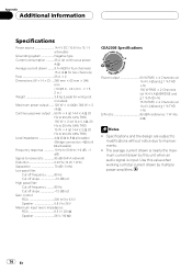
... ratio 95 dB (IHF-A network) Distortion 0.03 % (10 W, 1 kHz) Separation 70 dB (1 kHz) Low pass filter: Cut off frequency 80 Hz Cut off slope 12 dB/oct High pass filter: Cut off frequency 80 Hz Cut off slope 12 dB/oct Gain control: RCA 200 mV to 6.5 V Speaker 0.8 V to improvements. ! Use this value when working out total current drawn by this unit when an audio signal is input.
... ratio 95 dB (IHF-A network) Distortion 0.03 % (10 W, 1 kHz) Separation 70 dB (1 kHz) Low pass filter: Cut off frequency 80 Hz Cut off slope 12 dB/oct High pass filter: Cut off frequency 80 Hz Cut off slope 12 dB/oct Gain control: RCA 200 mV to 6.5 V Speaker 0.8 V to improvements. ! Use this value when working out total current drawn by this unit when an audio signal is input.
Owner's Manual
Page 45
..., Long Beach, California 90801-1540, U.S.A. PIONEER CORPORATION 4-1, MEGURO 1-CHOME, MEGURO-KU TOKYO 153-8654, JAPAN PIONEER ELECTRONICS (USA) INC. LTD. 253 Alexandra Road, #04-01, Singapore 159936 TEL: 65-6472-7555 PIONEER ELECTRONICS AUSTRALIA PTY. Blvd.Manuel Avila Camacho 138...;901-6 0852) 2848-6488 Published by Pioneer Corporation. All rights reserved. Copyright © 2008 by Pioneer Corporation. Publié par Pioneer Corporation. P.O. LTD. 178-184 Boundary Road, Braeside, Victoria 3195, Australia TEL: (03) 9586-6300 PIONEER ELECTRONICS OF CANADA, INC. 300 Allstate Parkway...
..., Long Beach, California 90801-1540, U.S.A. PIONEER CORPORATION 4-1, MEGURO 1-CHOME, MEGURO-KU TOKYO 153-8654, JAPAN PIONEER ELECTRONICS (USA) INC. LTD. 253 Alexandra Road, #04-01, Singapore 159936 TEL: 65-6472-7555 PIONEER ELECTRONICS AUSTRALIA PTY. Blvd.Manuel Avila Camacho 138...;901-6 0852) 2848-6488 Published by Pioneer Corporation. All rights reserved. Copyright © 2008 by Pioneer Corporation. Publié par Pioneer Corporation. P.O. LTD. 178-184 Boundary Road, Braeside, Victoria 3195, Australia TEL: (03) 9586-6300 PIONEER ELECTRONICS OF CANADA, INC. 300 Allstate Parkway...


