Owner's Manual
Page 2
Contents Before you start Information to User 3 After-sales service for Pioneer products 3 Visit our website 3 Before connecting/installing the amplifier 4 Setting the Unit What's what 5 Setting gain properly 5 Connecting the units Connection diagram 7 Before connecting the amplifier 7 About bridged mode 8 About suitable specification of speaker 8 Connecting ...input wire 10 Connecting the power terminal 11 Connecting the speaker output terminals 12 Installation Before installing the amplifier 13 Example of installation on the floor mat or chassis 13 Additional information Specifications 14 2 En
Contents Before you start Information to User 3 After-sales service for Pioneer products 3 Visit our website 3 Before connecting/installing the amplifier 4 Setting the Unit What's what 5 Setting gain properly 5 Connecting the units Connection diagram 7 Before connecting the amplifier 7 About bridged mode 8 About suitable specification of speaker 8 Connecting ...input wire 10 Connecting the power terminal 11 Connecting the speaker output terminals 12 Installation Before installing the amplifier 13 Example of installation on the floor mat or chassis 13 Additional information Specifications 14 2 En
Owner's Manual
Page 4
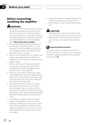
... product or cords as- Electrical shock could result in recreational vehicles, trucks or buses, check the battery voltage. ! Also, damage to the amplifier is located on this unit, smoke, and overheating could result from outside the vehicle. ! The surfaces of a special red battery and ground... chemicals listed on the enclosed warranty card. 4 En Always keep the volume low enough so that you start Before connecting/ installing the amplifier WARNING ! Section 01 Before you can hear sounds from contact with liquids. CAUTION ! Check the connections of the power supply and speakers...
... product or cords as- Electrical shock could result in recreational vehicles, trucks or buses, check the battery voltage. ! Also, damage to the amplifier is located on this unit, smoke, and overheating could result from outside the vehicle. ! The surfaces of a special red battery and ground... chemicals listed on the enclosed warranty card. 4 En Always keep the volume low enough so that you start Before connecting/ installing the amplifier WARNING ! Section 01 Before you can hear sounds from contact with liquids. CAUTION ! Check the connections of the power supply and speakers...
Owner's Manual
Page 5
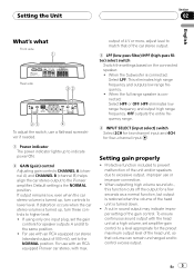
...using only one input plug, set the gain controls for the preout maximum output level of the head unit, so that of 500 mV), set amplifier gain control to a level appropriate for speaker outputs A and B to the NORMAL position. For use with an RCA equipped car stereo (standard output... outputting high volume sound etc., this function cuts off the output for four-channel input. output of the unit and/or speakers due to the Pioneer amplifier. A cut in sound output may indicate improper setting of the head unit is the NORMAL position. Default setting is turned down. ! For use...
...using only one input plug, set the gain controls for the preout maximum output level of the head unit, so that of 500 mV), set amplifier gain control to a level appropriate for speaker outputs A and B to the NORMAL position. For use with an RCA equipped car stereo (standard output... outputting high volume sound etc., this function cuts off the output for four-channel input. output of the unit and/or speakers due to the Pioneer amplifier. A cut in sound output may indicate improper setting of the head unit is the NORMAL position. Default setting is turned down. ! For use...
Owner's Manual
Page 6
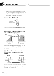
... gain of this unit Preout level: 2 V (Standard: 500mV) Above illustration shows NORMAL gain setting. Gain control of the amplifier the power changes only slightly. 6 En In such cases, please contact the nearest authorized Pioneer Service Station. Despite correct volume and gain settings, the unit sound still cuts out periodically. Signal waveform when...
... gain of this unit Preout level: 2 V (Standard: 500mV) Above illustration shows NORMAL gain setting. Gain control of the amplifier the power changes only slightly. 6 En In such cases, please contact the nearest authorized Pioneer Service Station. Despite correct volume and gain settings, the unit sound still cuts out periodically. Signal waveform when...
Owner's Manual
Page 7
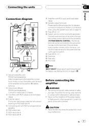
... A) × 2 c System remote control wire (sold separately) Connect male terminal of the car stereo (SYSTEM REMOTE CONTROL). Before connecting the amplifier WARNING ! CAUTION ! En 7 sive tape. To protect the wiring, wrap sections in adhesive tape. ! Never shorten any wires, the protection ...input select) switch must be connected to Connections when using the speaker input wire on page 5. Connecting the units Section 03 English Connection diagram 9 Amplifier with RCA output jacks (sold separately) 4 External output If only one input plug is limited. d Fuse (30 A) × 2 e...
... A) × 2 c System remote control wire (sold separately) Connect male terminal of the car stereo (SYSTEM REMOTE CONTROL). Before connecting the amplifier WARNING ! CAUTION ! En 7 sive tape. To protect the wiring, wrap sections in adhesive tape. ! Never shorten any wires, the protection ...input select) switch must be connected to Connections when using the speaker input wire on page 5. Connecting the units Section 03 English Connection diagram 9 Amplifier with RCA output jacks (sold separately) 4 External output If only one input plug is limited. d Fuse (30 A) × 2 e...
Owner's Manual
Page 8
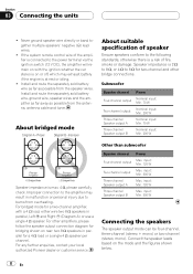
... on rear: two 8 W speakers in parallel, Left + and Right * (Diagram A) or use a single 4 W speaker. For bridged mode for a two-channel amplifier, with the ignition whether the car stereo is on the mode and the figures shown below. 8 En Speaker impedance is at rest or idling. ! For... any further enquiries, contact your local authorized Pioneer dealer or customer service. input: Min. 120 W Three-channel Speaker output B Max. Never ground speaker wire directly or band together multiple speakers' ...
... on rear: two 8 W speakers in parallel, Left + and Right * (Diagram A) or use a single 4 W speaker. For bridged mode for a two-channel amplifier, with the ignition whether the car stereo is on the mode and the figures shown below. 8 En Speaker impedance is at rest or idling. ! For... any further enquiries, contact your local authorized Pioneer dealer or customer service. input: Min. 120 W Three-channel Speaker output B Max. Never ground speaker wire directly or band together multiple speakers' ...
Owner's Manual
Page 10
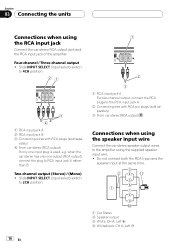
.../black: CH A, Left * Slide INPUT SELECT (input select) switch to 4CH position. 1 RCA input jack A For two-channel output, connect the RCA plugs to the amplifier using the RCA input jack Connect the car stereo RCA output jack and the RCA input jack of the... amplifier. rately) 4 From car stereo (RCA output) If only one output (RCA output), connect the plug to 2CH position. Four-channel / Three-channel output ! Slide INPUT ...
.../black: CH A, Left * Slide INPUT SELECT (input select) switch to 4CH position. 1 RCA input jack A For two-channel output, connect the RCA plugs to the amplifier using the RCA input jack Connect the car stereo RCA output jack and the RCA input jack of the... amplifier. rately) 4 From car stereo (RCA output) If only one output (RCA output), connect the plug to 2CH position. Four-channel / Three-channel output ! Slide INPUT ...
Owner's Manual
Page 11
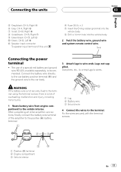
... including minor burns. 1 Route battery wire from engine compartment to wire ends. Use pliers, etc., to crimp lugs to the terminal. After completing all other amplifier connections, finally connect the battery wire terminal of this unit. 4 Fuse (30 A) × 2 5 Insert the O-ring rubber grommet into the vehicle body...: CH B, Right + 8 Violet/black: CH B, Right * 9 Green/black: CH B, Left * a Green: CH B, Left + b Speaker input connector To speaker input terminal of the amplifier to the positive (+) battery terminal. 1 Lug 2 Battery wire 3 Ground wire 4 Connect the wires to wires.
... including minor burns. 1 Route battery wire from engine compartment to wire ends. Use pliers, etc., to crimp lugs to the terminal. After completing all other amplifier connections, finally connect the battery wire terminal of this unit. 4 Fuse (30 A) × 2 5 Insert the O-ring rubber grommet into the vehicle body...: CH B, Right + 8 Violet/black: CH B, Right * 9 Green/black: CH B, Left * a Green: CH B, Left + b Speaker input connector To speaker input terminal of the amplifier to the positive (+) battery terminal. 1 Lug 2 Battery wire 3 Ground wire 4 Connect the wires to wires.
Owner's Manual
Page 13
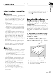
...) diameter hole 3 Floor mat or chassis En 13 fier, ensure the following during installation: - Installation Section 04 English Before installing the amplifier WARNING ! The optimal installation location differs depending on the floor in the manner specified. To ensure proper installation, use of the car, which...temporary connections and check to shut down. ! Places where it may damage the insulation, resulting in : - After installing the amplifier, confirm that the screw tip does not touch any parts other than those supplied are behind the panel and protect all cables ...
...) diameter hole 3 Floor mat or chassis En 13 fier, ensure the following during installation: - Installation Section 04 English Before installing the amplifier WARNING ! The optimal installation location differs depending on the floor in the manner specified. To ensure proper installation, use of the car, which...temporary connections and check to shut down. ! Places where it may damage the insulation, resulting in : - After installing the amplifier, confirm that the screw tip does not touch any parts other than those supplied are behind the panel and protect all cables ...
Owner's Manual
Page 14
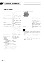
... signal is input. The average current drawn is nearly the maximum current drawn by this value when working out total current drawn by multiple power amplifiers. 14 En Appendix Additional information Specifications Power source 14.4 V DC (10.8 V to 15.1 V allowable) Grounding system Negative type Current consumption 35 A (at continuous power, 4 W) Average...
... signal is input. The average current drawn is nearly the maximum current drawn by this value when working out total current drawn by multiple power amplifiers. 14 En Appendix Additional information Specifications Power source 14.4 V DC (10.8 V to 15.1 V allowable) Grounding system Negative type Current consumption 35 A (at continuous power, 4 W) Average...

