
Service Manual
Page 1
... boards and other reproductive harm (California Health & Safety Code, Section 25249.5). PIONEER ELECTRONIC [EUROPE] N.V. GENERAL INFORMATION 16 7.1 DISASSEMBLY 16 8. JAN. 1998 Printed in solder, avoid unprotected skin contact with the solder. CRT2168 BRIDGEABLE FOUR-CHANNEL POWER AMPLIFIER GM-X424 X1R/UC, ES, EW GM-X324 X1R/UC CONTENTS 1. ELECTRICAL PARTS LIST 12 6. UC model CAUTION...
... boards and other reproductive harm (California Health & Safety Code, Section 25249.5). PIONEER ELECTRONIC [EUROPE] N.V. GENERAL INFORMATION 16 7.1 DISASSEMBLY 16 8. JAN. 1998 Printed in solder, avoid unprotected skin contact with the solder. CRT2168 BRIDGEABLE FOUR-CHANNEL POWER AMPLIFIER GM-X424 X1R/UC, ES, EW GM-X324 X1R/UC CONTENTS 1. ELECTRICAL PARTS LIST 12 6. UC model CAUTION...
Service Manual
Page 17
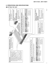
...Indicator The power indicator lights when the power is too low or distorts, adjust the gain control. Speaker Out A: Bass Boost Frequency Control (GM-X424) You can select a bass boost frequency from 40 to a position other than HPF. If the output is low even when the volume ...switch to the Pioneer amplifier. RCA Input Select Switch For two-channel input, slide this switch to a Pioneer car stereo with RCA output jacks. OPERATIONS AND SPECIFICATIONS - If there is distortion when the volume of the car stereo is connected to the right. SETTING THE UNIT GM-X424, GM-X324 BFC (...
...Indicator The power indicator lights when the power is too low or distorts, adjust the gain control. Speaker Out A: Bass Boost Frequency Control (GM-X424) You can select a bass boost frequency from 40 to a position other than HPF. If the output is low even when the volume ...switch to the Pioneer amplifier. RCA Input Select Switch For two-channel input, slide this switch to a Pioneer car stereo with RCA output jacks. OPERATIONS AND SPECIFICATIONS - If there is distortion when the volume of the car stereo is connected to the right. SETTING THE UNIT GM-X424, GM-X324 BFC (...
Service Manual
Page 18
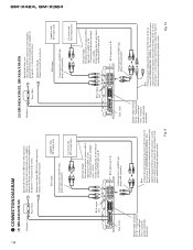
... remote control terminal, connect the male terminal to the blue wire of the amplifier to RCA input jack B. RCA input Connecting wires with RCA pin plugs (sold separately). (2) GM-X424/X1R/ES, GM-X424/X1R/EW Grommet Fuse (30A) Special red battery wire After making all other... connections at the amplifier, connect the battery wire terminal of the car stereo (SYSTEM REMOTE CONTROL). ...
... remote control terminal, connect the male terminal to the blue wire of the amplifier to RCA input jack B. RCA input Connecting wires with RCA pin plugs (sold separately). (2) GM-X424/X1R/ES, GM-X424/X1R/EW Grommet Fuse (30A) Special red battery wire After making all other... connections at the amplifier, connect the battery wire terminal of the car stereo (SYSTEM REMOTE CONTROL). ...
Service Manual
Page 19
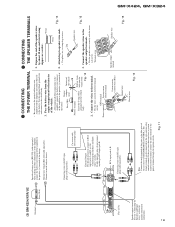
...and connect to wires. Fig. 12 2. Fig. 11 Battery wire Fig. 13 RCA input jack A, B Connecting wires with the amplifier and connect directly to use the special red battery wire supplied with RCA pin plugs (sold separately). CONNECTING THE POWER TERMINAL THE SPEAKER ... of ment the vehicle 1. GM-X424, GM-X324 19 (3) GM-X324/X1R/UC Grommet Fuse (30 A) Fuse (25 A) Speaker output terminal See the "Connecting the Speakers and Input wires" section for speaker connection instructions. After making all other connections to the amplifier, connect the battery wire terminal...
...and connect to wires. Fig. 12 2. Fig. 11 Battery wire Fig. 13 RCA input jack A, B Connecting wires with the amplifier and connect directly to use the special red battery wire supplied with RCA pin plugs (sold separately). CONNECTING THE POWER TERMINAL THE SPEAKER ... of ment the vehicle 1. GM-X424, GM-X324 19 (3) GM-X324/X1R/UC Grommet Fuse (30 A) Fuse (25 A) Speaker output terminal See the "Connecting the Speakers and Input wires" section for speaker connection instructions. After making all other connections to the amplifier, connect the battery wire terminal...
Service Manual
Page 21
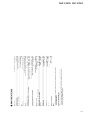
Use this unit when an audio signal is nearly the maximum current drawn by this value when working out total current drawn by multiple power amplifiers. GM-X424, GM-X324 21 SPECIFICATIONS Power source ...14.4 V DC (10.8 - 15.1 V allowable) Grounding system ...Negative type Current consumption ...18 A (at continuous power, 4 Ω) Average current drawn* ...5.5 A (4 Ω ...
Use this unit when an audio signal is nearly the maximum current drawn by this value when working out total current drawn by multiple power amplifiers. GM-X424, GM-X324 21 SPECIFICATIONS Power source ...14.4 V DC (10.8 - 15.1 V allowable) Grounding system ...Negative type Current consumption ...18 A (at continuous power, 4 Ω) Average current drawn* ...5.5 A (4 Ω ...

