Service Manual
Page 5
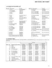
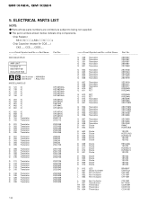
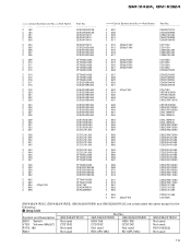
... System Remote Control See Contrast table (2) 49 Badge Unit See Contrast table (2) 50 Light Pipe Unit HXA0182 (2) CONTRAST TABLE GM-X424/X1R/UC, GM-X424/X1R/ES, GM-X424/X1R/EW and GM-X324/X1R/UC are constructed the same except for the following: Mark No. 6 8 9 11 28 Symbol and Description ...Panel Panel Heat Sink Amp Unit Pin Jack(CN852) X1R/UC HNB0053 HNB0048 HNR0091 HWH0054 HKB0002 Part No. Description 1 Screw 2 Screw(M3x6) 3 Screw...
... System Remote Control See Contrast table (2) 49 Badge Unit See Contrast table (2) 50 Light Pipe Unit HXA0182 (2) CONTRAST TABLE GM-X424/X1R/UC, GM-X424/X1R/ES, GM-X424/X1R/EW and GM-X324/X1R/UC are constructed the same except for the following: Mark No. 6 8 9 11 28 Symbol and Description ...Panel Panel Heat Sink Amp Unit Pin Jack(CN852) X1R/UC HNB0053 HNB0048 HNR0091 HWH0054 HKB0002 Part No. Description 1 Screw 2 Screw(M3x6) 3 Screw...
Service Manual
Page 6
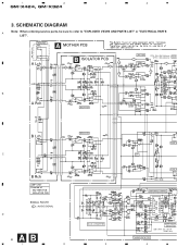
1 2 3 4 GM-X424, GM-X324 3. SCHEMATIC DIAGRAM A Note: When ordering service parts, be sure to refer to "EXPLODED VIEWS AND PARTS LIST" or "ELECTRICAL PARTS LIST". THRU-PUT A MOTHER PCB GM-X424 only A Lch B ISOLATOR PCB LPF / HPF R179, 180 : GM-X324 only VR153 : GM-X424 only BASS B A Rch ISOLATOR B Lch C ISOLATOR B Rch AMP UNIT Consists of MOTHER PCB ISOLATOR PCB SIGNAL ROUTE : AUDIO SIGNAL D 6 AB 1 2 DC-DC CONVERTER 3 FLAT A HPF FLAT A SWITCHING CONTROL OVER VOLTA DETECTOR S601, R641 : ES and EW models only THERMO-DETECTOR 4
1 2 3 4 GM-X424, GM-X324 3. SCHEMATIC DIAGRAM A Note: When ordering service parts, be sure to refer to "EXPLODED VIEWS AND PARTS LIST" or "ELECTRICAL PARTS LIST". THRU-PUT A MOTHER PCB GM-X424 only A Lch B ISOLATOR PCB LPF / HPF R179, 180 : GM-X324 only VR153 : GM-X424 only BASS B A Rch ISOLATOR B Lch C ISOLATOR B Rch AMP UNIT Consists of MOTHER PCB ISOLATOR PCB SIGNAL ROUTE : AUDIO SIGNAL D 6 AB 1 2 DC-DC CONVERTER 3 FLAT A HPF FLAT A SWITCHING CONTROL OVER VOLTA DETECTOR S601, R641 : ES and EW models only THERMO-DETECTOR 4
Service Manual
Page 7
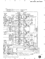
5 6 7 8 GM-X424, GM-X324 A BASS BOOST 4R7/50 BUFFER AMP PRE DRIVER POWER AMP OVER CURRENT DETECTOR OVER VOLTAGE DETECTOR 4R7/50 B FLAT AMP FLAT AMP MUTE MUTE POWER CONTROL / MUTE 22/50 R VOLTAGE TETECTOR 5 6 POWER DETECTOR C OVER CURRENT PROTECTOR & OVER VOLTAGE PROTECTOR ES and EW models only GROUND WIRE BATTERY WIRE SYSTEM REMOTE CONTROL D Fig. 3 A7 7 8
5 6 7 8 GM-X424, GM-X324 A BASS BOOST 4R7/50 BUFFER AMP PRE DRIVER POWER AMP OVER CURRENT DETECTOR OVER VOLTAGE DETECTOR 4R7/50 B FLAT AMP FLAT AMP MUTE MUTE POWER CONTROL / MUTE 22/50 R VOLTAGE TETECTOR 5 6 POWER DETECTOR C OVER CURRENT PROTECTOR & OVER VOLTAGE PROTECTOR ES and EW models only GROUND WIRE BATTERY WIRE SYSTEM REMOTE CONTROL D Fig. 3 A7 7 8
Service Manual
Page 12
.../_S___J,RS1/__S___J Chip Capacitor (except for CQS.....) CKS....., CCS....., CSZS..... =====Circuit Symbol and No.===Part Name GM-X424/X1R/UC Part No AMP UNIT Consists of MOTHER PCB ISOLATOR PCB A B Unit Number : HWH0054 Unit Name : Amp Unit MISCELLANEOUS IC 121 IC IC 122 IC IC 123 IC IC 151 IC IC 152 IC...
.../_S___J,RS1/__S___J Chip Capacitor (except for CQS.....) CKS....., CCS....., CSZS..... =====Circuit Symbol and No.===Part Name GM-X424/X1R/UC Part No AMP UNIT Consists of MOTHER PCB ISOLATOR PCB A B Unit Number : HWH0054 Unit Name : Amp Unit MISCELLANEOUS IC 121 IC IC 122 IC IC 123 IC IC 151 IC IC 152 IC...
Service Manual
Page 15
...;(C) CCS1242 CCS1242 CCS1242 Not used R179, 180 Not used Not used Not used RD1/10S223J R641 Not used RD1/4PU105J RD1/4PU105J Not used 15 GM-X424, GM-X324 =====Circuit Symbol and No.===Part Name C 163 C 164 C 301 C 302 C 303 C 304 C 305 C 306 C 307 C 308 C 309 C 310 C 311 ... CCSQCH470J50 CCSQCH470J50 CKSQYB103K50 CKSQYB103K50 CKSQYB103K50 CKSQYB103K50 CKSQYB471K50 CKSQYB471K50 CKSQYB471K50 CKSQYB471K50 CCSSL101J50 CCSSL101J50 CCSSL101J50 CCSSL101J50 CCH1036 GM-X424/X1R/UC, GM-X424/X1R/ES, GM-X424/X1R/EW and GM-X324/X1R/UC are constructed the same except for the following...
...;(C) CCS1242 CCS1242 CCS1242 Not used R179, 180 Not used Not used Not used RD1/10S223J R641 Not used RD1/4PU105J RD1/4PU105J Not used 15 GM-X424, GM-X324 =====Circuit Symbol and No.===Part Name C 163 C 164 C 301 C 302 C 303 C 304 C 305 C 306 C 307 C 308 C 309 C 310 C 311 ... CCSQCH470J50 CCSQCH470J50 CKSQYB103K50 CKSQYB103K50 CKSQYB103K50 CKSQYB103K50 CKSQYB471K50 CKSQYB471K50 CKSQYB471K50 CKSQYB471K50 CCSSL101J50 CCSSL101J50 CCSSL101J50 CCSSL101J50 CCH1036 GM-X424/X1R/UC, GM-X424/X1R/ES, GM-X424/X1R/EW and GM-X324/X1R/UC are constructed the same except for the following...
Service Manual
Page 16
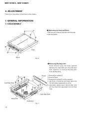
ADJUSTMENT There is no information to remove the Amp Unit from the Heat Sink. Removing the Amp Unit Some silicone glue has been applied between the Heat Sink and the Sub Heat Sink. therefore, to be shown in this chapter. 7. Panel C 1.... GENERAL INFORMATION 7.1 DISASSEMBLY A - Removing the Case and Panel 1. Remove six screws B and five screws C. 4. Remove six screws A, and then remove case. 2. Remove panel. Use 2 pcs. GM-X424, GM-X324 6. of screw B and insert them little by little until the Sub Heat Sink separates from the Heat Sink. Alternately tighten them into the two...
ADJUSTMENT There is no information to remove the Amp Unit from the Heat Sink. Removing the Amp Unit Some silicone glue has been applied between the Heat Sink and the Sub Heat Sink. therefore, to be shown in this chapter. 7. Panel C 1.... GENERAL INFORMATION 7.1 DISASSEMBLY A - Removing the Case and Panel 1. Remove six screws B and five screws C. 4. Remove six screws A, and then remove case. 2. Remove panel. Use 2 pcs. GM-X424, GM-X324 6. of screw B and insert them little by little until the Sub Heat Sink separates from the Heat Sink. Alternately tighten them into the two...


