
Service Manual
Page 5
...X1R/UC Not used Not used Not used 5 GM-X422 X1R/ES X1R/EW HDE4453 HDE4453 HEK0015 HEK0015 HDE4455 HDE4455 HNB0073 HNB0056 HNB0072 HNB0072 GM-X322 X1R/UC Not used Not used Not used HNB0058 HNB0051 14 Heat Sink 16 Amp Unit 26 Pin Jack(CN851) 27 Pin Jack(... 14 Heat Sink 15 Spacer HNB0016 See Contrast table (2) HNM0026 See Contrast table (2) HNV3975 16 Amp Unit 17 Screw 18 Screw 19 Plug(CN855) 20 Clamper See Contrast table (2) BMS30P060FZK BMS30P080FMC CKS1618 HNV0006 Mark No. GM-X422, GM-X322 (1) EXTERIOR SECTION PARTS LIST Mark No. Description 1 Screw 2 Screw(M3x6) 3 Screw(...
...X1R/UC Not used Not used Not used 5 GM-X422 X1R/ES X1R/EW HDE4453 HDE4453 HEK0015 HEK0015 HDE4455 HDE4455 HNB0073 HNB0056 HNB0072 HNB0072 GM-X322 X1R/UC Not used Not used Not used HNB0058 HNB0051 14 Heat Sink 16 Amp Unit 26 Pin Jack(CN851) 27 Pin Jack(... 14 Heat Sink 15 Spacer HNB0016 See Contrast table (2) HNM0026 See Contrast table (2) HNV3975 16 Amp Unit 17 Screw 18 Screw 19 Plug(CN855) 20 Clamper See Contrast table (2) BMS30P060FZK BMS30P080FMC CKS1618 HNV0006 Mark No. GM-X422, GM-X322 (1) EXTERIOR SECTION PARTS LIST Mark No. Description 1 Screw 2 Screw(M3x6) 3 Screw(...

Service Manual
Page 6
1 2 3 4 GM-X422, GM-X322 3. A MOTHER PCB SPEAKER INPUT LEVEL UC and ES models only 10/50 10/50 L C851, 852 UC, ES : 100P EW : 470P LPF / HPF R469, 470 : GM-X322 only VR452 : GM-X422 only BASS BOOST 4R7/50 MUTE B R L R R469 22k 22k R470 4R7/50 +15 REGULATOR C SWITCHING REGULATOR B ISOLATOR PCB SIGNAL ROUTE -15 REGULATOR : AUDIO SIGNAL AMP UNIT Consists of MOTHER PCB D ISOLATOR PCB 6 AB 1 2 3 THERMO-DETECTION 4 SCHEMATIC DIAGRAM Note: When ordering service parts, be sure to refer to "EXPLODED VIEWS AND PARTS LIST" or "ELECTRICAL PARTS A LIST".
1 2 3 4 GM-X422, GM-X322 3. A MOTHER PCB SPEAKER INPUT LEVEL UC and ES models only 10/50 10/50 L C851, 852 UC, ES : 100P EW : 470P LPF / HPF R469, 470 : GM-X322 only VR452 : GM-X422 only BASS BOOST 4R7/50 MUTE B R L R R469 22k 22k R470 4R7/50 +15 REGULATOR C SWITCHING REGULATOR B ISOLATOR PCB SIGNAL ROUTE -15 REGULATOR : AUDIO SIGNAL AMP UNIT Consists of MOTHER PCB D ISOLATOR PCB 6 AB 1 2 3 THERMO-DETECTION 4 SCHEMATIC DIAGRAM Note: When ordering service parts, be sure to refer to "EXPLODED VIEWS AND PARTS LIST" or "ELECTRICAL PARTS A LIST".

Service Manual
Page 7
5 6 7 8 GM-X422, GM-X322 A MUTE BUFFER AMP PRE DRIVER POWER AMP OVER CURRENT DETECTOR B 22/50 OVER CURRENT DETECTOR SWITCHING CONTROL ES and EW models only OVER VOLTAGE PROTECTOR POWER CONTROL / MUTE 5 6 C ES and EW models only HEK0015 15A GROUND WIRE BATTERY WIRE SYSTEM REMOTE CONTROL D Fig. 3 A7 7 8
5 6 7 8 GM-X422, GM-X322 A MUTE BUFFER AMP PRE DRIVER POWER AMP OVER CURRENT DETECTOR B 22/50 OVER CURRENT DETECTOR SWITCHING CONTROL ES and EW models only OVER VOLTAGE PROTECTOR POWER CONTROL / MUTE 5 6 C ES and EW models only HEK0015 15A GROUND WIRE BATTERY WIRE SYSTEM REMOTE CONTROL D Fig. 3 A7 7 8

Service Manual
Page 12
... RS1/_S___J,RS1/__S___J Chip Capacitor (except for CQS.....) CKS....., CCS....., CSZS..... =====Circuit Symbol and No.===Part Name GM-X422/X1R/UC AMP UNIT Consists of MOTHER PCB ISOLATOR PCB A B Unit Number : HWH0059 Unit Name : Amp Unit MISCELLANEOUS IC 121 IC IC 123 IC IC 451 IC IC 551 IC IC 651 IC IC... RS1/10S223J RS1/10S223J RS1/10S222J RS1/10S222J RS1/10S222J RS1/10S222J RS1/10S222J RS1/10S222J RS1/10S473J RS1/8S473J RS1/10S432J RS1/10S432J 12 GM-X422, GM-X322 5.
... RS1/_S___J,RS1/__S___J Chip Capacitor (except for CQS.....) CKS....., CCS....., CSZS..... =====Circuit Symbol and No.===Part Name GM-X422/X1R/UC AMP UNIT Consists of MOTHER PCB ISOLATOR PCB A B Unit Number : HWH0059 Unit Name : Amp Unit MISCELLANEOUS IC 121 IC IC 123 IC IC 451 IC IC 551 IC IC 651 IC IC... RS1/10S223J RS1/10S223J RS1/10S222J RS1/10S222J RS1/10S222J RS1/10S222J RS1/10S222J RS1/10S222J RS1/10S473J RS1/8S473J RS1/10S432J RS1/10S432J 12 GM-X422, GM-X322 5.
Service Manual
Page 14
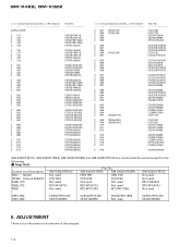
Symbol and Description GM-X422/X1R/UC GM-X422/X1R/ES GM-X422/X1R/EW GM-X322/X1R/UC S901 Switch Not used... C861, 862 CCSQCH101J50 CEAS100M50 CCSQCH101J50 CEAS100M50 CKSQYB471K50 Not used CCSQCH101J50 CEAS100M50 6. ADJUSTMENT There is no information to be shown in this chapter. 14 GM-X422, GM-X322 =====Circuit Symbol and No.===Part Name CAPACITORS C 121 C 122 C 125 C 126 C 129 C 130 C 131 C 132 C...CEAS100M50 CQMA102J50 CQMA102J50 CFTNA224J50 CQMA102J50 CKSYB103K50 GM-X422/X1R/UC, GM-X422/X1R/ES, GM-X422/X1R/EW and GM-X322/X1R/UC are constructed the same except for the following...
Symbol and Description GM-X422/X1R/UC GM-X422/X1R/ES GM-X422/X1R/EW GM-X322/X1R/UC S901 Switch Not used... C861, 862 CCSQCH101J50 CEAS100M50 CCSQCH101J50 CEAS100M50 CKSQYB471K50 Not used CCSQCH101J50 CEAS100M50 6. ADJUSTMENT There is no information to be shown in this chapter. 14 GM-X422, GM-X322 =====Circuit Symbol and No.===Part Name CAPACITORS C 121 C 122 C 125 C 126 C 129 C 130 C 131 C 132 C...CEAS100M50 CQMA102J50 CQMA102J50 CFTNA224J50 CQMA102J50 CKSYB103K50 GM-X422/X1R/UC, GM-X422/X1R/ES, GM-X422/X1R/EW and GM-X322/X1R/UC are constructed the same except for the following...

Service Manual
Page 15
7. Removing the Case and Panel 1. Removing the Amp Unit Some silicone glue has been applied between the Heat sink and the Sub Heat Sink. Use 2 pcs. Alternately tighten them into the two holes ... insert them little by little until the Sub Heat Sink separates from the Heat Sink. 1. Remove panel. A Panel Case Fig. 6 B C Amp Unit Sub Heat Sink C B - GENERAL INFORMATION 7.1 DISASSEMBLY A GM-X422, GM-X322 - therefore, to remove the Amp Unit from the Heat Sink. Remove four screws B and Three screws C. 2. Sub Heat Sink Heat Sink Fig. 7 15
7. Removing the Case and Panel 1. Removing the Amp Unit Some silicone glue has been applied between the Heat sink and the Sub Heat Sink. Use 2 pcs. Alternately tighten them into the two holes ... insert them little by little until the Sub Heat Sink separates from the Heat Sink. 1. Remove panel. A Panel Case Fig. 6 B C Amp Unit Sub Heat Sink C B - GENERAL INFORMATION 7.1 DISASSEMBLY A GM-X422, GM-X322 - therefore, to remove the Amp Unit from the Heat Sink. Remove four screws B and Three screws C. 2. Sub Heat Sink Heat Sink Fig. 7 15


