
Owners Manual
Page 3
...power to the system OFF and check the connection of trouble When the unit does not operate properly, contact your dealer or the nearest authorized PIONEER Service Station. WARNING • Always use the special red battery and ground wire [RD-223], which is wet. • For traffic ...panel when drilling a hole for purchasing this manual. Also, do not touch the amplifier when it is sold battery wire or the amplifier fuse blows. Be sure to the car body. • Do not touch the amplifier with wet hands. DEUTSCH FRANÇAIS ITALIANO NEDERLANDS 2 Before attempting operation, ...
...power to the system OFF and check the connection of trouble When the unit does not operate properly, contact your dealer or the nearest authorized PIONEER Service Station. WARNING • Always use the special red battery and ground wire [RD-223], which is wet. • For traffic ...panel when drilling a hole for purchasing this manual. Also, do not touch the amplifier when it is sold battery wire or the amplifier fuse blows. Be sure to the car body. • Do not touch the amplifier with wet hands. DEUTSCH FRANÇAIS ITALIANO NEDERLANDS 2 Before attempting operation, ...

Owners Manual
Page 4
... outputs A and B to the same position. • When using with an RCA equipped Pioneer car stereo with an RCA equipped car stereo (standard output of 500 mV), set the gain controls to the right. 3 Normally, set to the Pioneer amplifier. Setting the Unit Gain Control Adjusting the gain controls A and B will help match...
... outputs A and B to the same position. • When using with an RCA equipped Pioneer car stereo with an RCA equipped car stereo (standard output of 500 mV), set the gain controls to the right. 3 Normally, set to the Pioneer amplifier. Setting the Unit Gain Control Adjusting the gain controls A and B will help match...

Owners Manual
Page 6
... fail to work when it may go dead if the engine is at rest or idling. • If the system remote control wire of the amplifier is on for vehicles with cable clamps or adhesive tape. If they do not conform, they may be different colors even if they will blow... products may catch fire, emit smoke or become damaged, resulting in case of both products and connect cords that wires will be connected to the amplifier should . • Never feed power to other equipment by cutting the insulation of the power supply wire to tap from the wire. Install and route...
... fail to work when it may go dead if the engine is at rest or idling. • If the system remote control wire of the amplifier is on for vehicles with cable clamps or adhesive tape. If they do not conform, they may be different colors even if they will blow... products may catch fire, emit smoke or become damaged, resulting in case of both products and connect cords that wires will be connected to the amplifier should . • Never feed power to other equipment by cutting the insulation of the power supply wire to tap from the wire. Install and route...

Owners Manual
Page 7
... output jacks Front side Speaker input terminal See the "Using the Speaker Input" section. The female terminal can be connected to metal body or chassis. Amplifier with RCA pin plugs (sold separately). Speaker output terminal See the "Connecting the Speaker wires" section for speaker connection instructions. RCA input Connecting wires with... ESPAÑOL Connection Diagram Fuse (30 A) Grommet Fuse (30 A) Special red battery wire [RD-223] (sold separately) After making all other connections at the amplifier, connect the battery wire terminal of the...
... output jacks Front side Speaker input terminal See the "Using the Speaker Input" section. The female terminal can be connected to metal body or chassis. Amplifier with RCA pin plugs (sold separately). Speaker output terminal See the "Connecting the Speaker wires" section for speaker connection instructions. RCA input Connecting wires with... ESPAÑOL Connection Diagram Fuse (30 A) Grommet Fuse (30 A) Special red battery wire [RD-223] (sold separately) After making all other connections at the amplifier, connect the battery wire terminal of the...

Owners Manual
Page 8
...Pass the battery wire from the engine compartment to the interior of the vehicle. • After making all other connections to the amplifier, connect the battery wire terminal of the battery. GND terminal Power terminal System remote control terminal System remote control wire Ground wire Battery.... 2. Twist Connecting the Speaker Output Terminals 1. Twist 10 mm 3. Lug Speaker wire 7 Connect the wires to the positive (+) terminal of the amplifier to the terminal. • Fix the wires securely with the terminal screws. Lugs not supplied. • Use pliers, etc., to crimp lugs to...
...Pass the battery wire from the engine compartment to the interior of the vehicle. • After making all other connections to the amplifier, connect the battery wire terminal of the battery. GND terminal Power terminal System remote control terminal System remote control wire Ground wire Battery.... 2. Twist Connecting the Speaker Output Terminals 1. Twist 10 mm 3. Lug Speaker wire 7 Connect the wires to the positive (+) terminal of the amplifier to the terminal. • Fix the wires securely with the terminal screws. Lugs not supplied. • Use pliers, etc., to crimp lugs to...

Owners Manual
Page 9
...; Fix the speaker wires securely with the terminal screws. FRANÇAIS ITALIANO NEDERLANDS 8 Push on the terminal cover. Connect the speaker wires to the amplifier using the supplied speaker input connector. • Do not connect both the RCA input and the speaker input at the same time. 7 Connections when using...
...; Fix the speaker wires securely with the terminal screws. FRANÇAIS ITALIANO NEDERLANDS 8 Push on the terminal cover. Connect the speaker wires to the amplifier using the supplied speaker input connector. • Do not connect both the RCA input and the speaker input at the same time. 7 Connections when using...
Owners Manual
Page 12
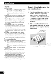
...for installation of installation on the floor mat or on the carpet or directly to be located. 2. Example of the amplifier. Secure the amplifier at the point marked, and install the amplifier, either on the chassis 1. Tapping-screws (4 × 18 mm) Floor mat or chassis Drill a 2.5 mm ... 2.5 mm diameter holes at a sufficiently rigid location. • Make temporary connections first and check that the amplifier and the system operate properly. • After installing the amplifier, confirm that the screw tip does not touch any parts other than the supplied ones are used, they may...
...for installation of installation on the floor mat or on the carpet or directly to be located. 2. Example of the amplifier. Secure the amplifier at the point marked, and install the amplifier, either on the chassis 1. Tapping-screws (4 × 18 mm) Floor mat or chassis Drill a 2.5 mm ... 2.5 mm diameter holes at a sufficiently rigid location. • Make temporary connections first and check that the amplifier and the system operate properly. • After installing the amplifier, confirm that the screw tip does not touch any parts other than the supplied ones are used, they may...
Owners Manual
Page 13
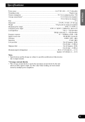
Use this value when working out total current drawn by this unit when an audio signal is nearly the maximum current drawn by multiple power amplifiers. 12 FRANÇAIS ITALIANO NEDERLANDS ENGLISH ESPAÑOL DEUTSCH Specifications Power source ...14.4 V DC (10.8 - 15.1 V allowable) Grounding system ...Negative type Current consumption ......
Use this value when working out total current drawn by this unit when an audio signal is nearly the maximum current drawn by multiple power amplifiers. 12 FRANÇAIS ITALIANO NEDERLANDS ENGLISH ESPAÑOL DEUTSCH Specifications Power source ...14.4 V DC (10.8 - 15.1 V allowable) Grounding system ...Negative type Current consumption ......

