Owner's Manual
Page 4
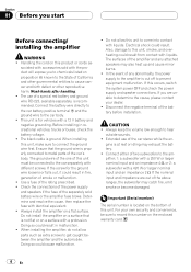
... wire first. The black cable is ground. Always install the amplifier on the enclosed warranty card. 4 En When installing the amplifier, do not allow this unit. In the event of this unit to the car separately with liquids. CAUTION ! gine is at rest or idling... V battery and negative grounding. Electrical shock could cause malfunction. ! Connect either of the car stereo while the en- Wash hands after handling. ! Do not allow parts such as - Always keep the volume low enough to the amplifier; 1: a subwoofer with a 250 W or larger nominal input and an impedance 4 W,...
... wire first. The black cable is ground. Always install the amplifier on the enclosed warranty card. 4 En When installing the amplifier, do not allow this unit. In the event of this unit to the car separately with liquids. CAUTION ! gine is at rest or idling... V battery and negative grounding. Electrical shock could cause malfunction. ! Connect either of the car stereo while the en- Wash hands after handling. ! Do not allow parts such as - Always keep the volume low enough to the amplifier; 1: a subwoofer with a 250 W or larger nominal input and an impedance 4 W,...
Owner's Manual
Page 5
... can select a bass boost level from 40 Hz to 240 Hz. To ensure continuous sound output with the head unit at a high volume, set amplifier gain control to a level appropriate for a few seconds as a normal function, but output is restored when the volume of 500 mV), set to ... Station. For use or improper connection. ! Protective function included to excessive output, improper use with an RCA equipped Pioneer car stereo, with an RCA equipped car stereo (standard output of the head unit is turned down. ! A cut off the output for the preout maximum output level of the head unit...
... can select a bass boost level from 40 Hz to 240 Hz. To ensure continuous sound output with the head unit at a high volume, set amplifier gain control to a level appropriate for a few seconds as a normal function, but output is restored when the volume of 500 mV), set to ... Station. For use or improper connection. ! Protective function included to excessive output, improper use with an RCA equipped Pioneer car stereo, with an RCA equipped car stereo (standard output of the head unit is turned down. ! A cut off the output for the preout maximum output level of the head unit...
Owner's Manual
Page 7
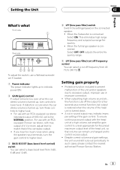
... lacks a system remote control terminal, Before connecting the amplifier WARNING ! CAUTION ! Never band together multiple speaker'snega- En 7 sive tape. Never cut the insulation of the car stereo. to the auto-antenna relay control terminal. The female terminal can be connected to ground. ! Refer to... 5 Connecting wire with the ignition whether the car stereo is on or off, which may malfunction. ! If the system remote control wire of the wire is connected to the power terminal via the ignition switch (12 V DC), the amplifier will remain on with RCA pin plugs (sold...
... lacks a system remote control terminal, Before connecting the amplifier WARNING ! CAUTION ! Never band together multiple speaker'snega- En 7 sive tape. Never cut the insulation of the car stereo. to the auto-antenna relay control terminal. The female terminal can be connected to ground. ! Refer to... 5 Connecting wire with the ignition whether the car stereo is on or off, which may malfunction. ! If the system remote control wire of the wire is connected to the power terminal via the ignition switch (12 V DC), the amplifier will remain on with RCA pin plugs (sold...
Owner's Manual
Page 8
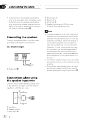
... pin cord from a headunit are to be connected together synchronously, connect the head unit and all amplifiers via the system remote control wire. ! When the headunit is turned on the car stereo, not the amplifier. ! In such cases, please use a system remote control wire (sold battery wire as far ... from the antenna, antenna cable and tuner. Connecting the speakers Connect the speaker leads to suit the mode according to the amplifier using the speaker input wire Connect the car stereo speaker output wires to the figures shown below. This function may not work with RCA pin cord...
... pin cord from a headunit are to be connected together synchronously, connect the head unit and all amplifiers via the system remote control wire. ! When the headunit is turned on the car stereo, not the amplifier. ! In such cases, please use a system remote control wire (sold battery wire as far ... from the antenna, antenna cable and tuner. Connecting the speakers Connect the speaker leads to suit the mode according to the amplifier using the speaker input wire Connect the car stereo speaker output wires to the figures shown below. This function may not work with RCA pin cord...
Owner's Manual
Page 9
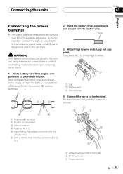
... positive terminal (+) and the ground wire to wire ends. Twist 3 Attach lugs to the car body. Fix the wires securely with the terminal screws. 1 Positive (+) terminal 2 Engine compartment 3 Vehicle interior 4 Fuse (30 A) × 2 5 Insert the O-... Drill a 14 mm hole into the vehicle body (1/2 in.) . 1 System remote control terminal 2 GND terminal 3 Power terminal En 9 After completing all other amplifier connections, finally connect the battery wire terminal of overheating, malfunction and injury, including minor burns. 1 Route battery wire from engine compartment to the vehicle interior...
... positive terminal (+) and the ground wire to wire ends. Twist 3 Attach lugs to the car body. Fix the wires securely with the terminal screws. 1 Positive (+) terminal 2 Engine compartment 3 Vehicle interior 4 Fuse (30 A) × 2 5 Insert the O-... Drill a 14 mm hole into the vehicle body (1/2 in.) . 1 System remote control terminal 2 GND terminal 3 Power terminal En 9 After completing all other amplifier connections, finally connect the battery wire terminal of overheating, malfunction and injury, including minor burns. 1 Route battery wire from engine compartment to the vehicle interior...
Owner's Manual
Page 11
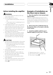
...18 mm) into the screw holes and push on the floor mat or chassis 1 Place the amplifier in fire. ! pending on the chassis. 3 Install the amplifier with a floor mat or carpet. ! When drilling to install the amplifier, always confirm no parts are to be easily removed. 1 Tapping-screws (4 mm × 18... from hot places, such as the gear shift and seat rails. ! To ensure proper heat dissipation of installation on the screws with operation of the car, which can be located. 2 Drill 2.5 mm (1/8 in .) diameter hole 3 Floor mat or chassis En 11 Install tapping screws in such a...
...18 mm) into the screw holes and push on the floor mat or chassis 1 Place the amplifier in fire. ! pending on the chassis. 3 Install the amplifier with a floor mat or carpet. ! When drilling to install the amplifier, always confirm no parts are to be easily removed. 1 Tapping-screws (4 mm × 18... from hot places, such as the gear shift and seat rails. ! To ensure proper heat dissipation of installation on the screws with operation of the car, which can be located. 2 Drill 2.5 mm (1/8 in .) diameter hole 3 Floor mat or chassis En 11 Install tapping screws in such a...


