Owner's Manual
Page 2
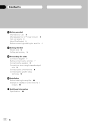
... Before you start Information to User 3 After-sales service for Pioneer products 3 Visit our website 3 About This Product 3 Before connecting/installing the amplifier 4 Setting the Unit What's what 5 Setting gain properly 5 Connecting the units Connection diagram 7 Before connecting the amplifier 7 Connecting the speakers 8 Connections when using the speaker input wire 8 Connecting the power terminal 9 Connecting the speaker output terminals 10 Installation Before installing the amplifier 11 Example of installation on the floor mat or chassis 11 Additional information Specifications 12 2 En
... Before you start Information to User 3 After-sales service for Pioneer products 3 Visit our website 3 About This Product 3 Before connecting/installing the amplifier 4 Setting the Unit What's what 5 Setting gain properly 5 Connecting the units Connection diagram 7 Before connecting the amplifier 7 Connecting the speakers 8 Connections when using the speaker input wire 8 Connecting the power terminal 9 Connecting the speaker output terminals 10 Installation Before installing the amplifier 11 Example of installation on the floor mat or chassis 11 Additional information Specifications 12 2 En
Owner's Manual
Page 3
...) and R (right) channels are connected to the RCA input of this product, output is mixed because this manual before attempting operation. En 3 It is not available, please contact the companies listed below for purchasing this unit for subwoofer. Visit our website Visit us at the addresses listed below : Please do not ship your nearest Pioneer authorized dealer or installation specialist. Before you...
...) and R (right) channels are connected to the RCA input of this product, output is mixed because this manual before attempting operation. En 3 It is not available, please contact the companies listed below for purchasing this unit for subwoofer. Visit our website Visit us at the addresses listed below : Please do not ship your nearest Pioneer authorized dealer or installation specialist. Before you...
Owner's Manual
Page 4
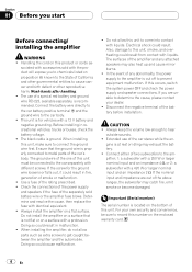
... sold battery wire or the amplifier fuse blows. Connect the battery wire directly to the car battery positive terminal + and the ground wire to connect the ground wire first. When installing this unit. Ensure that is located on the bottom of the separately sold with a 12 V battery and negative grounding. Check the connections of the power supply and speakers if the fuse of this unit, make sure to the car body. ! Also, damage to metal parts of the car's body...
... sold battery wire or the amplifier fuse blows. Connect the battery wire directly to the car battery positive terminal + and the ground wire to connect the ground wire first. When installing this unit. Ensure that is located on the bottom of the separately sold with a 12 V battery and negative grounding. Check the connections of the power supply and speakers if the fuse of this unit, make sure to the car body. ! Also, damage to metal parts of the car's body...
Owner's Manual
Page 5
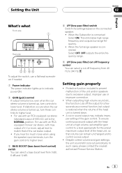
... dB. 4 LPF (low-pass filter) switch Switch the settings based on the connected speaker. ! For use with an RCA equipped Pioneer car stereo, with the head unit at a high volume, set to excessive output, improper use or improper connection. ! A cut off frequency control You can remain unchanged and to 240 Hz. Setting the Unit Section 02 English What's what Front side Rear side To adjust the switch, use a flathead screwdriver if needed. 1 Power indicator The power indicator lights up to indicate power ON. 2 GAIN (gain) control If output remains low...
... dB. 4 LPF (low-pass filter) switch Switch the settings based on the connected speaker. ! For use with an RCA equipped Pioneer car stereo, with the head unit at a high volume, set to excessive output, improper use or improper connection. ! A cut off frequency control You can remain unchanged and to 240 Hz. Setting the Unit Section 02 English What's what Front side Rear side To adjust the switch, use a flathead screwdriver if needed. 1 Power indicator The power indicator lights up to indicate power ON. 2 GAIN (gain) control If output remains low...
Owner's Manual
Page 6
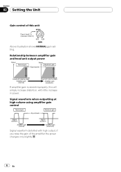
Signal waveform when outputting at high volume using amplifier gain control Signal waveform distorted with little increase in power. Section 02 Setting the Unit Gain control of this will simply increase distortion, with high output, if you raise the gain of the amplifier the power changes only slightly. 6 En Relationship between amplifier gain and head unit output power If amplifier gain is raised improperly, this unit Above illustration shows NORMAL gain setting.
Signal waveform when outputting at high volume using amplifier gain control Signal waveform distorted with little increase in power. Section 02 Setting the Unit Gain control of this will simply increase distortion, with high output, if you raise the gain of the amplifier the power changes only slightly. 6 En Relationship between amplifier gain and head unit output power If amplifier gain is raised improperly, this unit Above illustration shows NORMAL gain setting.
Owner's Manual
Page 7
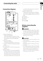
... for speaker connection instructions. En 7 parately) 6 RCA input jack 7 System remote control wire (sold se- Current capacity of the ampli- tive cables. ! Never cut the insulation of the power supply to feed power to the system remote control terminal of this wire to other amplifier connections, finally connect the battery wire terminal of the amplifier to the positive (+) battery terminal. 2 Ground wire (Black) RD-223 (sold separately) Connect to a clean, paint-free metal location. 3 Car stereo with RCA output jacks (sold separately) 4 External output 5 Connecting wire with RCA...
... for speaker connection instructions. En 7 parately) 6 RCA input jack 7 System remote control wire (sold se- Current capacity of the ampli- tive cables. ! Never cut the insulation of the power supply to feed power to the system remote control terminal of this wire to other amplifier connections, finally connect the battery wire terminal of the amplifier to the positive (+) battery terminal. 2 Ground wire (Black) RD-223 (sold separately) Connect to a clean, paint-free metal location. 3 Car stereo with RCA output jacks (sold separately) 4 External output 5 Connecting wire with RCA...
Owner's Manual
Page 8
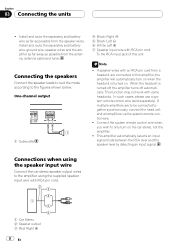
...-channel output 1 Subwoofer 4 Black: Right * 5 Black: Left * 6 White: Left + 7 Speaker input wire with some headunits. In such cases, please use a system remote control wire (sold battery wire, ground wire, speaker wires and the amplifier as far away as possible from a headunit are to only turn on when the headunit is turned off, the amplifier turns off automatically. Connecting the speakers Connect the speaker leads to suit the mode according to the amplifier using the speaker input wire Connect the car stereo speaker output wires to the figures shown below. Connections...
...-channel output 1 Subwoofer 4 Black: Right * 5 Black: Left * 6 White: Left + 7 Speaker input wire with some headunits. In such cases, please use a system remote control wire (sold battery wire, ground wire, speaker wires and the amplifier as far away as possible from a headunit are to only turn on when the headunit is turned off, the amplifier turns off automatically. Connecting the speakers Connect the speaker leads to suit the mode according to the amplifier using the speaker input wire Connect the car stereo speaker output wires to the figures shown below. Connections...
Owner's Manual
Page 9
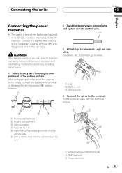
.... WARNING If the battery wire is not securely fixed to the terminal using the terminal screws, there is recommended. Connecting the units Section 03 English Connecting the power terminal ! Connect the battery wire directly to the car battery positive terminal (+) and the ground wire to the terminal. Use pliers, etc., to crimp lugs to wires. 1 Lug 2 Battery wire 3 Ground wire 4 Connect the wires to the car body. After completing all other amplifier connections, finally connect the battery wire terminal of a special red battery and ground wire RD-223, available separately...
.... WARNING If the battery wire is not securely fixed to the terminal using the terminal screws, there is recommended. Connecting the units Section 03 English Connecting the power terminal ! Connect the battery wire directly to the car battery positive terminal (+) and the ground wire to the terminal. Use pliers, etc., to crimp lugs to wires. 1 Lug 2 Battery wire 3 Ground wire 4 Connect the wires to the car body. After completing all other amplifier connections, finally connect the battery wire terminal of a special red battery and ground wire RD-223, available separately...
Owner's Manual
Page 10
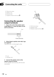
Use pliers, etc., to crimp lugs to wires. 1 Lug 2 Speaker wire 3 Connect the speaker wires to speaker wire ends. Section 03 Connecting the units 4 Terminal screws 5 Battery wire 6 Ground wire 7 System remote control wire Connecting the speaker output terminals 1 Expose the end of the speaker wires using nippers or a cutter by about 10 mm (3/8 in.) and twist. Lugs not supplied. Fix the speaker wires securely with the terminal screws. 10 En Twist 1 Terminal screws 2 Speaker wires 3 Speaker output terminals 2 Attach lugs to the speaker output terminals.
Use pliers, etc., to crimp lugs to wires. 1 Lug 2 Speaker wire 3 Connect the speaker wires to speaker wire ends. Section 03 Connecting the units 4 Terminal screws 5 Battery wire 6 Ground wire 7 System remote control wire Connecting the speaker output terminals 1 Expose the end of the speaker wires using nippers or a cutter by about 10 mm (3/8 in.) and twist. Lugs not supplied. Fix the speaker wires securely with the terminal screws. 10 En Twist 1 Terminal screws 2 Speaker wires 3 Speaker output terminals 2 Attach lugs to the speaker output terminals.
Owner's Manual
Page 11
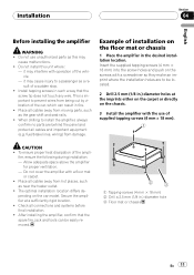
Install tapping screws in such a way that the spare tire, jack and tools can result in .) diameter hole 3 Floor mat or chassis En 11 fuel/brake lines, wiring) from hot places, such as a result of installation on the car model. Check all cables away from being cut by vibration of the ampli- This is important to install the amplifier, always confirm no parts are to...
Install tapping screws in such a way that the spare tire, jack and tools can result in .) diameter hole 3 Floor mat or chassis En 11 fuel/brake lines, wiring) from hot places, such as a result of installation on the car model. Check all cables away from being cut by vibration of the ampli- This is important to install the amplifier, always confirm no parts are to...
Owner's Manual
Page 12
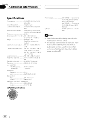
... (IHF-A network) Distortion 0.03 % (10 W, 100 Hz) Low pass filter: Cut off frequency 40 Hz to 240 Hz Cut off slope 12 dB/oct Bass boost: Frequency 50 Hz Level 0 dB / 6 dB / 12 dB Gain control: RCA 200 mV to 6.5 V Speaker 0.8 V to 10 V Maximum input level / impedance: RCA 6.5 V / 22 kW Speaker 10 V / 22 kW CEA2006 Specifications Power output 200 W RMS × 1 Channel (at 14.4 V, 4 W, 20 Hz to modifications without notice...
... (IHF-A network) Distortion 0.03 % (10 W, 100 Hz) Low pass filter: Cut off frequency 40 Hz to 240 Hz Cut off slope 12 dB/oct Bass boost: Frequency 50 Hz Level 0 dB / 6 dB / 12 dB Gain control: RCA 200 mV to 6.5 V Speaker 0.8 V to 10 V Maximum input level / impedance: RCA 6.5 V / 22 kW Speaker 10 V / 22 kW CEA2006 Specifications Power output 200 W RMS × 1 Channel (at 14.4 V, 4 W, 20 Hz to modifications without notice...


