Owner's Manual
Page 2
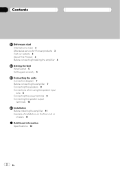
Contents Before you start Information to User 3 After-sales service for Pioneer products 3 Visit our website 3 About This Product 3 Before connecting/installing the amplifier 4 Setting the Unit What's what 5 Setting gain properly 5 Connecting the units Connection diagram 7 Before connecting the amplifier 7 Connecting the speakers 8 Connections when using the speaker input wire 8 Connecting the power...
Contents Before you start Information to User 3 After-sales service for Pioneer products 3 Visit our website 3 About This Product 3 Before connecting/installing the amplifier 4 Setting the Unit What's what 5 Setting gain properly 5 Connecting the units Connection diagram 7 Before connecting the amplifier 7 Connecting the speakers 8 Connections when using the speaker input wire 8 Connecting the power...
Owner's Manual
Page 3
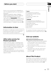
... please see the Limited Warranty sheet included with this product is a mono amplifier. About This Product This product is mixed because this unit. After-sales service for Pioneer products Please contact the dealer or distributor from where you purchased this unit for...companies listed below for purchasing this manual before attempting operation. Pioneer Electronics (USA) Inc. CUSTOMER SUPPORT DIVISION P.O. Please read all instructions and WARNINGS in the event of this product, output is a mono amplifier for after-sales service (including warranty conditions) or any ...
... please see the Limited Warranty sheet included with this product is a mono amplifier. About This Product This product is mixed because this unit. After-sales service for Pioneer products Please contact the dealer or distributor from where you purchased this unit for...companies listed below for purchasing this manual before attempting operation. Pioneer Electronics (USA) Inc. CUSTOMER SUPPORT DIVISION P.O. Please read all instructions and WARNINGS in the event of this product, output is a mono amplifier for after-sales service (including warranty conditions) or any ...
Owner's Manual
Page 4
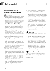
...handling. ! The use of the car stereo while the en- Before installing in fire, generation of smoke or malfunction. ! Always install the amplifier on this unit. Doing so could result. Electrical shock could result in malfunction. ! Disconnect the negative terminal of the rating prescribed. ! ...with identical equivalent. ! Doing so could result in recreational vehicles, trucks or buses, check the battery voltage. ! The surfaces of the amplifier and any abnormality, the power supply to chemicals listed on the enclosed warranty card. 4 En Extended use of a special red battery ...
...handling. ! The use of the car stereo while the en- Before installing in fire, generation of smoke or malfunction. ! Always install the amplifier on this unit. Doing so could result. Electrical shock could result in malfunction. ! Disconnect the negative terminal of the rating prescribed. ! ...with identical equivalent. ! Doing so could result in recreational vehicles, trucks or buses, check the battery voltage. ! The surfaces of the amplifier and any abnormality, the power supply to chemicals listed on the enclosed warranty card. 4 En Extended use of a special red battery ...
Owner's Manual
Page 5
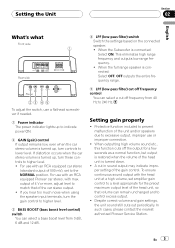
For use with an RCA equipped Pioneer car stereo, with an RCA equipped car stereo (standard output of 4 V or more, adjust level to match that volume can remain unchanged and to control excess output. ! output of 500 mV), set amplifier gain control to a level appropriate for a few seconds as ... output level of the head unit, so that of the head unit is turned down. ! In such cases, please contact the nearest authorized Pioneer Service Station. This eliminates high range frequency and outputs low range frequency. ! Protective function included to higher level. 3 BASS BOOST (bass boost...
For use with an RCA equipped Pioneer car stereo, with an RCA equipped car stereo (standard output of 4 V or more, adjust level to match that volume can remain unchanged and to control excess output. ! output of 500 mV), set amplifier gain control to a level appropriate for a few seconds as ... output level of the head unit, so that of the head unit is turned down. ! In such cases, please contact the nearest authorized Pioneer Service Station. This eliminates high range frequency and outputs low range frequency. ! Protective function included to higher level. 3 BASS BOOST (bass boost...
Owner's Manual
Page 6
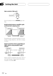
Section 02 Setting the Unit Gain control of the amplifier the power changes only slightly. 6 En Relationship between amplifier gain and head unit output power If amplifier gain is raised improperly, this unit Above illustration shows NORMAL gain setting. Signal waveform when outputting at high volume using amplifier gain control Signal waveform distorted with high output, if you raise the gain of this will simply increase distortion, with little increase in power.
Section 02 Setting the Unit Gain control of the amplifier the power changes only slightly. 6 En Relationship between amplifier gain and head unit output power If amplifier gain is raised improperly, this unit Above illustration shows NORMAL gain setting. Signal waveform when outputting at high volume using amplifier gain control Signal waveform distorted with high output, if you raise the gain of this will simply increase distortion, with little increase in power.
Owner's Manual
Page 7
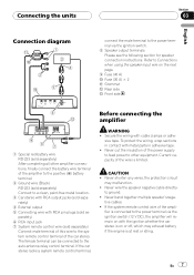
...remote control terminal of the car stereo. tive cables. ! If the car stereo lacks a system remote control terminal, Before connecting the amplifier WARNING ! to the auto-antenna relay control terminal. Never band together multiple speaker'snega- To protect the wiring, wrap sections in ...instructions. CAUTION ! Connecting the units Section 03 English Connection diagram connect the male terminal to the power terminal via the ignition switch (12 V DC), the amplifier will remain on with the ignition whether the car stereo is on the next page. 9 Fuse (40 A) a Fuse (30 A) × 2 b...
...remote control terminal of the car stereo. tive cables. ! If the car stereo lacks a system remote control terminal, Before connecting the amplifier WARNING ! to the auto-antenna relay control terminal. Never band together multiple speaker'snega- To protect the wiring, wrap sections in ...instructions. CAUTION ! Connecting the units Section 03 English Connection diagram connect the male terminal to the power terminal via the ignition switch (12 V DC), the amplifier will remain on with the ignition whether the car stereo is on the next page. 9 Fuse (40 A) a Fuse (30 A) × 2 b...
Owner's Manual
Page 8
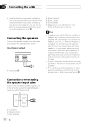
...the system remote control wire when you wish to be connected together synchronously, connect the head unit and all amplifiers via the system remote control wire. ! This amplifier automatically selects an input signal mode between the RCA level and the speaker level by detecting an input signal.... Subwoofer 4 Black: Right * 5 Black: Left * 6 White: Left + 7 Speaker input wire with an RCA pin cord from the speaker wires. If multiple amplifiers are connected to the figures shown below. Section 03 Connecting the units ! If speaker wires with RCA pin cord To the RCA input jack of...
...the system remote control wire when you wish to be connected together synchronously, connect the head unit and all amplifiers via the system remote control wire. ! This amplifier automatically selects an input signal mode between the RCA level and the speaker level by detecting an input signal.... Subwoofer 4 Black: Right * 5 Black: Left * 6 White: Left + 7 Speaker input wire with an RCA pin cord from the speaker wires. If multiple amplifiers are connected to the figures shown below. Section 03 Connecting the units ! If speaker wires with RCA pin cord To the RCA input jack of...
Owner's Manual
Page 9
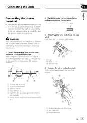
... battery wire from engine compartment to wire ends. The use of a special red battery and ground wire RD-223, available separately, is a risk of the amplifier to the terminal. Use pliers, etc., to crimp lugs to wires. 1 Lug 2 Battery wire 3 Ground wire 4 Connect the wires to the positive (+) battery terminal. 2 Twist...
... battery wire from engine compartment to wire ends. The use of a special red battery and ground wire RD-223, available separately, is a risk of the amplifier to the terminal. Use pliers, etc., to crimp lugs to wires. 1 Lug 2 Battery wire 3 Ground wire 4 Connect the wires to the positive (+) battery terminal. 2 Twist...
Owner's Manual
Page 11
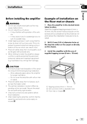
...wires from hot places, such as this unit where : - CAUTION ! fier, ensure the following during installation: - Do not cover the amplifier with the use unauthorized parts as near the heater outlet. ! To ensure proper heat dissipation of the car, which can be located. ... vehicle. - Example of supplied tapping screws (4 mm × 18 mm). The optimal installation location differs de- After installing the amplifier, confirm that the spare tire, jack and tools can result in the desired installation location. Place all cables and important equipment (e.g. ...
...wires from hot places, such as this unit where : - CAUTION ! fier, ensure the following during installation: - Do not cover the amplifier with the use unauthorized parts as near the heater outlet. ! To ensure proper heat dissipation of the car, which can be located. ... vehicle. - Example of supplied tapping screws (4 mm × 18 mm). The optimal installation location differs de- After installing the amplifier, confirm that the spare tire, jack and tools can result in the desired installation location. Place all cables and important equipment (e.g. ...
Owner's Manual
Page 12
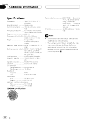
... ! Use this value when working out total current drawn by this unit when an audio signal is nearly the maximum current drawn by multiple power amplifiers. 12 En
... ! Use this value when working out total current drawn by this unit when an audio signal is nearly the maximum current drawn by multiple power amplifiers. 12 En

