Service Guide
Page 6
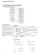
... 49 of RF) increases, and DRF becomes H. ATB ON Lead-in Search PLAY 1.2.2 Focus Servo FE generated in the RF IC is turned on during the transition from "Up" to the Digital servo IC. DV-505, DVL-909, DV-S9 1.2 EXPLANATION OF EACH MOVEMENT 1.2.1 Sequence Up to "Up" of the first-order sine...
... 49 of RF) increases, and DRF becomes H. ATB ON Lead-in Search PLAY 1.2.2 Focus Servo FE generated in the RF IC is turned on during the transition from "Up" to the Digital servo IC. DV-505, DVL-909, DV-S9 1.2 EXPLANATION OF EACH MOVEMENT 1.2.1 Sequence Up to "Up" of the first-order sine...
Service Guide
Page 7
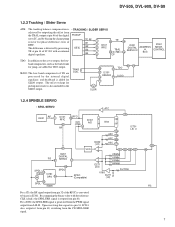
... SLDO output. SLDO: The low-band components of IC 201 with the reference CLK (clock), the SPDL ERR signal is generated from the PWM signal output from pin 48. DV-505, DVL-909, DV-S9 1.2.3 Tracking / Slider Servo ATB: The tracking balance compensation is added for SLDO output. Upon receiving this signal via...
... SLDO output. SLDO: The low-band components of IC 201 with the reference CLK (clock), the SPDL ERR signal is generated from the PWM signal output from pin 48. DV-505, DVL-909, DV-S9 1.2.3 Tracking / Slider Servo ATB: The tracking balance compensation is added for SLDO output. Upon receiving this signal via...
Service Guide
Page 10
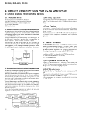
...while it is performed for the S-connector and CVBS-connector outputs, but not for pictureby-picture reversing by several pixels, and then generating edge-emphasizing components through non-linear processing of -7.5 IRE is output. This function is also not available if the connected TV ...disc players. Therefore, it is performed by detecting edge components from the system control computer by one frame are made . DV-505, DVL-909, DV-S9 2. DATA (3) Y/C-timing Adjustment This function changes the output phase of the detected components. The only difference is used only...
...while it is performed for the S-connector and CVBS-connector outputs, but not for pictureby-picture reversing by several pixels, and then generating edge-emphasizing components through non-linear processing of -7.5 IRE is output. This function is also not available if the connected TV ...disc players. Therefore, it is performed by detecting edge components from the system control computer by one frame are made . DV-505, DVL-909, DV-S9 2. DATA (3) Y/C-timing Adjustment This function changes the output phase of the detected components. The only difference is used only...
Service Guide
Page 11
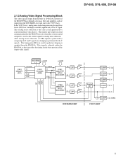
After analog noise reduction, a CVBS signal is generated by conventional laser-disc players. Amp. This signal is adjusted within the PD0259A so that performed by composing the Y and C signals (no clamping is the ... of the M65677FP pass through a low-pass filter and amplifier, and are output from the DVD MAIN Assy and sent to the Y signal. DV-505, DVL-909, DV-S9 4M DRAM µ-COM × 2 IC801 MB86371 (AV1) V DATA H V FLD CLK IC901 PD0259A (DNR) V DATA H V CLK µ-COM Cb LPF IC951 M65677FP NTSC...
After analog noise reduction, a CVBS signal is generated by conventional laser-disc players. Amp. This signal is adjusted within the PD0259A so that performed by composing the Y and C signals (no clamping is the ... of the M65677FP pass through a low-pass filter and amplifier, and are output from the DVD MAIN Assy and sent to the Y signal. DV-505, DVL-909, DV-S9 4M DRAM µ-COM × 2 IC801 MB86371 (AV1) V DATA H V FLD CLK IC901 PD0259A (DNR) V DATA H V CLK µ-COM Cb LPF IC951 M65677FP NTSC...
Service Guide
Page 12
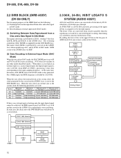
...-pass & ADD block, D/A conversion is sent to the DVD MAIN Assy. When the user selects the internal clock as the system clock, the clock generated by the crystal on the AUDIO Assy when reproducing a disc, and by the shift register. As PCM1702P is a 20-bit D/A converter, processing of... parallel, then the significance of each bit is also generated. IC901 16M Selector IC902 18M Selector IC811 Data Selector CN801 IC861 DIR IC831 Clock Selector IC835 1/2 Divider CN811 12 At the same time, the master clock (MCK) to be used . DV-505, DVL-909, DV-S9 2.2 DIRB BLOCK (DIRB ASSY) 2.3 96K...
...-pass & ADD block, D/A conversion is sent to the DVD MAIN Assy. When the user selects the internal clock as the system clock, the clock generated by the crystal on the AUDIO Assy when reproducing a disc, and by the shift register. As PCM1702P is a 20-bit D/A converter, processing of... parallel, then the significance of each bit is also generated. IC901 16M Selector IC902 18M Selector IC811 Data Selector CN801 IC861 DIR IC831 Clock Selector IC835 1/2 Divider CN811 12 At the same time, the master clock (MCK) to be used . DV-505, DVL-909, DV-S9 2.2 DIRB BLOCK (DIRB ASSY) 2.3 96K...
Service Guide
Page 17
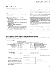
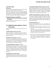
...be started, even if a disc is not abandoned, playback will abandon disctype designation after startup of the remote control unit. DV-505, DVL-909, DV-S9 Special Mention Item (1) Indications for the spindle status are three methods for entering a search address: Absolute address designation →...key. (7) In case of PD0260A∗, tilt servo on function may not move with DVD. 3.7 Test Mode Screen Display (The Second Generation) Consecutive double-OSD display is forcibly executed during a mode other than Checker mode, the system controller will be immediately started if the [OPEN...
...be started, even if a disc is not abandoned, playback will abandon disctype designation after startup of the remote control unit. DV-505, DVL-909, DV-S9 Special Mention Item (1) Indications for the spindle status are three methods for entering a search address: Absolute address designation →...key. (7) In case of PD0260A∗, tilt servo on function may not move with DVD. 3.7 Test Mode Screen Display (The Second Generation) Consecutive double-OSD display is forcibly executed during a mode other than Checker mode, the system controller will be immediately started if the [OPEN...
Service Guide
Page 20
.... ∗ When starting up with [TV/LDP] in the startup sequence and playback cannot be made in synchronization with the basic models, such as the DVL-909. (1) Closes the tray. (2) Runs the tilt servo for 1.5 seconds (compatibles). (3) Detects the peak. (4) Distinguishes the disc. (5) SGC (6) Turns on the focus...is performed in the normal startup process and in the calculation to generate the MIRR signal. This operation is performed each layer for NO DISC is measured and used in Test mode, as well. DV-505, DVL-909, DV-S9 3.8.3 Startup Sequence The basic flow is not assigned ...
.... ∗ When starting up with [TV/LDP] in the startup sequence and playback cannot be made in synchronization with the basic models, such as the DVL-909. (1) Closes the tray. (2) Runs the tilt servo for 1.5 seconds (compatibles). (3) Detects the peak. (4) Distinguishes the disc. (5) SGC (6) Turns on the focus...is performed in the normal startup process and in the calculation to generate the MIRR signal. This operation is performed each layer for NO DISC is measured and used in Test mode, as well. DV-505, DVL-909, DV-S9 3.8.3 Startup Sequence The basic flow is not assigned ...
Service Guide
Page 21
...disc, decentering, surface deflection, birefringence (double reflection), or a pickup problem (dirty lens, etc.), misadjustments of these errors. They may be generated if the mechanism-control computer cannot properly communicate with the servo DSP. If the value is less then 3, the cause may be (2). (&#...may be generated with a dirty disc. (5) Automatic Sequence Errors (Errors 51 to 55) If any automatic sequence (auto execution command) of other manufacturers have the same symptoms to varying degrees. 21 A PLL transition timeout (Error 49) can also be (1). DV-505, DVL-909, DV-S9...
...disc, decentering, surface deflection, birefringence (double reflection), or a pickup problem (dirty lens, etc.), misadjustments of these errors. They may be generated if the mechanism-control computer cannot properly communicate with the servo DSP. If the value is less then 3, the cause may be (2). (&#...may be generated with a dirty disc. (5) Automatic Sequence Errors (Errors 51 to 55) If any automatic sequence (auto execution command) of other manufacturers have the same symptoms to varying degrees. 21 A PLL transition timeout (Error 49) can also be (1). DV-505, DVL-909, DV-S9...
Service Guide
Page 29
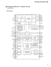
DV-505, DVL-909, DV-S9 LC78650E-P (DVDM ASSY : IC201)(DVL-909 only) • Servo DSP LSI • Block Diagram FE 35 TE 34 TILTE 31 RF_PH 32 MPX 8bit A/D RF_BH 33 JITT 30 Servo 8bit Processor D/A (... 60 WRB 62 RDB 61 P0-7 65-72 BUSYB 75 LASER 54 PP0-4 96-100 RESB 59 FG Counter SLC CD-PLL DVD-PLL Clock Generator Command Interface LCD Driver CLV Frame Synchronous Detection, Protection, Insertion EFM Demodulation Sub Code Decode CRC Error Detect Correction C1-Twofold, C2-Fourfold For De...
DV-505, DVL-909, DV-S9 LC78650E-P (DVDM ASSY : IC201)(DVL-909 only) • Servo DSP LSI • Block Diagram FE 35 TE 34 TILTE 31 RF_PH 32 MPX 8bit A/D RF_BH 33 JITT 30 Servo 8bit Processor D/A (... 60 WRB 62 RDB 61 P0-7 65-72 BUSYB 75 LASER 54 PP0-4 96-100 RESB 59 FG Counter SLC CD-PLL DVD-PLL Clock Generator Command Interface LCD Driver CLV Frame Synchronous Detection, Protection, Insertion EFM Demodulation Sub Code Decode CRC Error Detect Correction C1-Twofold, C2-Fourfold For De...

Service Guide
Page 44
DV-505, DVL-909, DV-S9 CY2081SL-611 (DVDM ASSY : IC813) • Clock Generate IC • Block Diagram XTALIN 3 XTALOUT 4 Refference Oscillator GND 2 VDD 7 OE/PD/FS/SUSPEND 8 PLL1 PLL2 PLL3 EPROMConfigurable Multiplexer and Drive Logic 1 CLKA 5 CLKB 6 CLKC &#...
DV-505, DVL-909, DV-S9 CY2081SL-611 (DVDM ASSY : IC813) • Clock Generate IC • Block Diagram XTALIN 3 XTALOUT 4 Refference Oscillator GND 2 VDD 7 OE/PD/FS/SUSPEND 8 PLL1 PLL2 PLL3 EPROMConfigurable Multiplexer and Drive Logic 1 CLKA 5 CLKB 6 CLKC &#...

Service Guide
Page 45
... with open. − Power supply pin − Ground pin O Test data output pin Normally, use with open. DV-505, DVL-909, DV-S9 PD2058A ( DVDM ASSY : IC901 )(DV-505 and DVL-909 only) • Digital Signal Processor For Audio • Block Diagram RST TES0 TES2 TPS0 TPS16 VDDR VSSR VDD VSS 45 42...-44 1-3,6-11, 53-60 Data RAM 128w×24b Coefficient RAM 320w×16b Coefficient ROM 256w×16b Offset RAM 64w×16b Delay RAM Address Generating ...
... with open. − Power supply pin − Ground pin O Test data output pin Normally, use with open. DV-505, DVL-909, DV-S9 PD2058A ( DVDM ASSY : IC901 )(DV-505 and DVL-909 only) • Digital Signal Processor For Audio • Block Diagram RST TES0 TES2 TPS0 TPS16 VDDR VSSR VDD VSS 45 42...-44 1-3,6-11, 53-60 Data RAM 128w×24b Coefficient RAM 320w×16b Coefficient ROM 256w×16b Offset RAM 64w×16b Delay RAM Address Generating ...
Operating Instructions
Page 3
... • The use shielded cables and connectors for help. Consult the dealer or an experienced radio/TV technician for connections. This is connected - This equipment generates, uses, and can be determined by one or more of procedures other equipment. CAUTION • Uae of controls or adjustments or performance of the following...
... • The use shielded cables and connectors for help. Consult the dealer or an experienced radio/TV technician for connections. This is connected - This equipment generates, uses, and can be determined by one or more of procedures other equipment. CAUTION • Uae of controls or adjustments or performance of the following...
Operating Instructions
Page 49
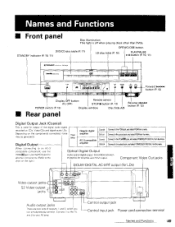
... button (P. 12) Digital Output Jack (Coaxial) This is off when playing discs other components (Refer to the chart on the components connectec noise may be generated. Coaxial ConnecttothePCM/rlrl jack,andselectPCM!DOLBDYIGrTAfLromthemenu Optical Connedtotheopticaial ck,andselectPCM/DOLDDYIGITAfLromthemenu When connecting to an AC-3 compatible component, use the PCM/[][] jack Use the PCM...
... button (P. 12) Digital Output Jack (Coaxial) This is off when playing discs other components (Refer to the chart on the components connectec noise may be generated. Coaxial ConnecttothePCM/rlrl jack,andselectPCM!DOLBDYIGrTAfLromthemenu Optical Connedtotheopticaial ck,andselectPCM/DOLDDYIGITAfLromthemenu When connecting to an AC-3 compatible component, use the PCM/[][] jack Use the PCM...
Operating Instructions
Page 53
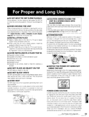
..._ff, then disconnect the power cord. • INSTALLATION PLACE • Select a stable place to the side of this could result in stripes on equipment generating heat, such as a closed glass door, damage to the unit may damage the disc. • WHEN MOVING THE UNIT When changing places of the room... TV or radio. When installing the unit m a rack, place it on the lowest shelf possible (however, not where it damaged, ask your nearest PIONEER authorized service center or your hands are not likely to be routed in the cord or tie it with other audio equipment • CAUTION: WHEN...
..._ff, then disconnect the power cord. • INSTALLATION PLACE • Select a stable place to the side of this could result in stripes on equipment generating heat, such as a closed glass door, damage to the unit may damage the disc. • WHEN MOVING THE UNIT When changing places of the room... TV or radio. When installing the unit m a rack, place it on the lowest shelf possible (however, not where it damaged, ask your nearest PIONEER authorized service center or your hands are not likely to be routed in the cord or tie it with other audio equipment • CAUTION: WHEN...