Owner's Manual
Page 2
...light) D3-4-2-1-7c_A_En WARNING To prevent a fire hazard, do not place any 13 amp socket. D3-4-2-1-3_A_En VENTILATION CAUTION When installing this Pioneer product. D3-4-2-1-7b_A_En This product complies with a moulded three pin mains plug for future reference. Check the power cord once in a safe... place for your local authorities for the unit, you lose the fuse cover the plug must be used inside a carrying case or DJ booth, separate it with the coloured markings identifying the terminals in a location which is marked with the letter L or ...
...light) D3-4-2-1-7c_A_En WARNING To prevent a fire hazard, do not place any 13 amp socket. D3-4-2-1-3_A_En VENTILATION CAUTION When installing this Pioneer product. D3-4-2-1-7b_A_En This product complies with a moulded three pin mains plug for future reference. Check the power cord once in a safe... place for your local authorities for the unit, you lose the fuse cover the plug must be used inside a carrying case or DJ booth, separate it with the coloured markings identifying the terminals in a location which is marked with the letter L or ...
Owner's Manual
Page 3
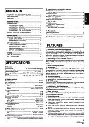
...input is detected. 6 Other functions ¶ A control cable can be used to connect the unit to a Pioneer DJ CD player, thus allowing playback to be linked to operation of the fader... kill function is performed with the same type of 32-bit DSP as used in the DJM-1000 and DJM-800, thus eliminating any loss in linkage to the BPM (Beats Per ... HANDLING 2 SPECIFICATIONS 3 FEATURES 3 BEFORE USING CONNECTIONS 4 CONNECTION PANEL 4 CONNECTING INPUTS 5 CONNECTING OUTPUTS 5 CONNECTING THE POWER CORD 5 NAMES AND FUNCTIONS OF PARTS 6 OPERATIONS MIXER OPERATIONS 8 BASIC OPERATIONS 8 FADER START...
...input is detected. 6 Other functions ¶ A control cable can be used to connect the unit to a Pioneer DJ CD player, thus allowing playback to be linked to operation of the fader... kill function is performed with the same type of 32-bit DSP as used in the DJM-1000 and DJM-800, thus eliminating any loss in linkage to the BPM (Beats Per ... HANDLING 2 SPECIFICATIONS 3 FEATURES 3 BEFORE USING CONNECTIONS 4 CONNECTION PANEL 4 CONNECTING INPUTS 5 CONNECTING OUTPUTS 5 CONNECTING THE POWER CORD 5 NAMES AND FUNCTIONS OF PARTS 6 OPERATIONS MIXER OPERATIONS 8 BASIC OPERATIONS 8 FADER START...
Owner's Manual
Page 4
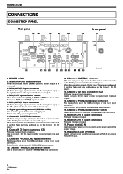
...cue on the channel 2 DJ CD player. 12. When this connection is made , the DJ mixer's fader lever can be used to perform fader start play and back cue on the channel 1 DJ CD player. 8. When this switch is not a safety grounding terminal. 7. Use to connect stereo headphones ... (L) channel of channel 2 PHONO/LINE input connectors. 15. MIC/AUX input selector switch When this connection is made , the DJ mixer's fader lever can be used to [AUX], the MIC1 and MIC2 input connectors function as AUX(L) and AUX(R) input connectors. 5. POWER switch 2. CONNECTIONS CONNECTIONS...
...cue on the channel 2 DJ CD player. 12. When this connection is made , the DJ mixer's fader lever can be used to perform fader start play and back cue on the channel 1 DJ CD player. 8. When this switch is not a safety grounding terminal. 7. Use to connect stereo headphones ... (L) channel of channel 2 PHONO/LINE input connectors. 15. MIC/AUX input selector switch When this connection is made , the DJ mixer's fader lever can be used to [AUX], the MIC1 and MIC2 input connectors function as AUX(L) and AUX(R) input connectors. 5. POWER switch 2. CONNECTIONS CONNECTIONS...
Owner's Manual
Page 5
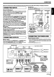
CONNECTING INPUTS Pioneer DJ CD players Connect a DJ CD player's audio output connectors to one of the channel 1 to 2 CD ...output connectors to one of the player, then connect the plug to a standard wall outlet or to [LINE] except when using an analog turntable LR RL RL RL RL Microphone 2 Microphone 1 R L Electronic instrument, CD player, etc. (phone ... DJ CD player DJ CD player 5 En Microphone The MIC1 and MIC2 jacks can also be used to connect headphones with line level output connectors. Connect the component's L channel to MIC1 (AUX(L)) jack and the R channel to the DJM-400's...
CONNECTING INPUTS Pioneer DJ CD players Connect a DJ CD player's audio output connectors to one of the channel 1 to 2 CD ...output connectors to one of the player, then connect the plug to a standard wall outlet or to [LINE] except when using an analog turntable LR RL RL RL RL Microphone 2 Microphone 1 R L Electronic instrument, CD player, etc. (phone ... DJ CD player DJ CD player 5 En Microphone The MIC1 and MIC2 jacks can also be used to connect headphones with line level output connectors. Connect the component's L channel to MIC1 (AUX(L)) jack and the R channel to the DJM-400's...
Owner's Manual
Page 6
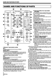
... input) are selected. PHONO 1/LINE 1: PHONO/LINE input connectors are selected. ¶ The connection panel's PHONO/LINE switch is used to switch the function of the channel 2 connectors between phonograph input (analog turntable input) and line input (line level input). 11... CD 1 PHONO 1 /LINE 1 TRIM CD 2 PHONO 2 /LINE 2 TRIM MASTER LEVEL 13 dial (LOW) Use to adjust the bass (low-range) frequency sound for each channel (includes kill function). (Adjustable 24 3 2 CHANNEL DJ MIXER 3 14 range: -∞ to +9 dB) 0 0 7 Channel level indicators MIC 2 LEVEL + 9 BEAT ...
... input) are selected. PHONO 1/LINE 1: PHONO/LINE input connectors are selected. ¶ The connection panel's PHONO/LINE switch is used to switch the function of the channel 2 connectors between phonograph input (analog turntable input) and line input (line level input). 11... CD 1 PHONO 1 /LINE 1 TRIM CD 2 PHONO 2 /LINE 2 TRIM MASTER LEVEL 13 dial (LOW) Use to adjust the bass (low-range) frequency sound for each channel (includes kill function). (Adjustable 24 3 2 CHANNEL DJ MIXER 3 14 range: -∞ to +9 dB) 0 0 7 Channel level indicators MIC 2 LEVEL + 9 BEAT ...
Owner's Manual
Page 7
...button indicator lights brightly (P. 8). When effects are enabled (ON), the button flashes. Microphone input control 24 Microphone 1 level control dial (MIC 1 LEVEL) Use to adjust the volume of microphone 1. (Adjustable range -∞ to 0 dB) When the connection panel's MIC/AUX switch is set to [AUX], this ... During in the BEAT/BANK button will be erased. 20 Effect selector (DELAY/ECHO/FILTER/FLANGER/ PHASER/ROBOT/ROLL/IN-LOOP SAMPLER) Use to select desired type of high-range sound is maximized. (Adjustable range 0 dB to monitor with headphones. When rotated fully clockwise, ...
...button indicator lights brightly (P. 8). When effects are enabled (ON), the button flashes. Microphone input control 24 Microphone 1 level control dial (MIC 1 LEVEL) Use to adjust the volume of microphone 1. (Adjustable range -∞ to 0 dB) When the connection panel's MIC/AUX switch is set to [AUX], this ... During in the BEAT/BANK button will be erased. 20 Effect selector (DELAY/ECHO/FILTER/FLANGER/ PHASER/ROBOT/ROLL/IN-LOOP SAMPLER) Use to select desired type of high-range sound is maximized. (Adjustable range 0 dB to monitor with headphones. When rotated fully clockwise, ...
Owner's Manual
Page 8
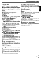
.... [Selecting Stereo or Monaural] When the connection panel's STEREO/MONO switch is set to one of two characteristic curves. 7 Use the cross fader selector switch to select the desired cross fader response curve. ¶ At the center position ( ), the ...) MASTER(MONO) MASTER(MONO) 2. Set the connection panel's MIC/AUX switch to adjust sound tone. [Headphones Output] 1. Use the microphone equalizer dial (EQ) to [MIC]. 2. MIXER OPERATIONS (BASIC OPERATIONS) MIXER OPERATIONS BASIC OPERATIONS 2 MIC 3 TRIM 4 HI, MID, LOW 1 POWER MASTER BEAT EFFECTS 7 MASTER LEVEL HEADPHONES 5 ...
.... [Selecting Stereo or Monaural] When the connection panel's STEREO/MONO switch is set to one of two characteristic curves. 7 Use the cross fader selector switch to select the desired cross fader response curve. ¶ At the center position ( ), the ...) MASTER(MONO) MASTER(MONO) 2. Set the connection panel's MIC/AUX switch to adjust sound tone. [Headphones Output] 1. Use the microphone equalizer dial (EQ) to [MIC]. 2. MIXER OPERATIONS (BASIC OPERATIONS) MIXER OPERATIONS BASIC OPERATIONS 2 MIC 3 TRIM 4 HI, MID, LOW 1 POWER MASTER BEAT EFFECTS 7 MASTER LEVEL HEADPHONES 5 ...
Owner's Manual
Page 9
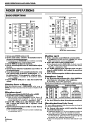
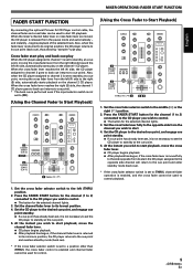
... (2) side toward the left (THRU) position. 2. MIXER OPERATIONS (FADER START FUNCTION) English FADER START FUNCTION By connecting the optional Pioneer DJ CD Player control cable, the channel fader and cross fader can be used to start. 4. When the mixer's channel fader lever or cross fader lever are moved,... the CD player is enabled and channel fader cannot be used for control. 9 En Set...
... (2) side toward the left (THRU) position. 2. MIXER OPERATIONS (FADER START FUNCTION) English FADER START FUNCTION By connecting the optional Pioneer DJ CD Player control cable, the channel fader and cross fader can be used to start. 4. When the mixer's channel fader lever or cross fader lever are moved,... the CD player is enabled and channel fader cannot be used for control. 9 En Set...
Owner's Manual
Page 10
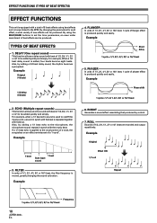
... OF BEAT EFFECTS) EFFECT FUNCTIONS This unit is equipped with beat of 1/2, 3/4, 1/1, 2/1 or 4/1 to be added quickly and simply. By using beat effects and in-loops linked to cutoff the input sound, a sound in synch with the beat is moved, greatly changing the sound coloration....parameters for each effect, a wide variety of 1/2, 3/4, 1/1, 2/1 or 4/1 beat are recorded and output repetitively. For example, When a 1/2 beat delay sound is used to the BPM. Also, by a robot. 7. For example, when a 1/1 beat echo sound is added, four beats become eight beats. Example 1 beat 1 ...
... OF BEAT EFFECTS) EFFECT FUNCTIONS This unit is equipped with beat of 1/2, 3/4, 1/1, 2/1 or 4/1 to be added quickly and simply. By using beat effects and in-loops linked to cutoff the input sound, a sound in synch with the beat is moved, greatly changing the sound coloration....parameters for each effect, a wide variety of 1/2, 3/4, 1/1, 2/1 or 4/1 beat are recorded and output repetitively. For example, When a 1/2 beat delay sound is used to the BPM. Also, by a robot. 7. For example, when a 1/1 beat echo sound is added, four beats become eight beats. Example 1 beat 1 ...
Owner's Manual
Page 11
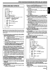
... is first turned ON, the function defaults to OFF). ¶ The ON/OFF button flashes when effects are recorded in up to sample record. 3. Use the BEAT/PITCH buttons (-, +) to select the beat multiple to which you wish to five memory banks, and played as loops in 1-step increments....value will flash. Set the effect selector to an effect other than 4/1 (16), the 4/1(16) button will flash. ¶ During use the TAP mode for manual BPM input. [Using the TAP Button for details regarding the various effects. 3. However, the 3/4 multiple can be selected from the BPM, the BEAT/BANK ...
... is first turned ON, the function defaults to OFF). ¶ The ON/OFF button flashes when effects are recorded in up to sample record. 3. Use the BEAT/PITCH buttons (-, +) to select the beat multiple to which you wish to five memory banks, and played as loops in 1-step increments....value will flash. Set the effect selector to an effect other than 4/1 (16), the 4/1(16) button will flash. ¶ During use the TAP mode for manual BPM input. [Using the TAP Button for details regarding the various effects. 3. However, the 3/4 multiple can be selected from the BPM, the BEAT/BANK ...
Owner's Manual
Page 12
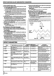
... standby, the button will flash slowly at intervals. ¶ When 4 beats of sound at the measured BPM have already been recorded, and cannot be used again unless their recorded contents are lighted. ¶ The indicator in unit of 1/1 to 16/1 relative to sample record, press one of BPM time.... button indicator will change from slow flashing to steadily lighted. [To Playback a Recorded Sample] 1 Set the effect selector switch to [IN-LOOP SAMPLER]. 2 Use the effect channel selector to choose the channel for in the selected BEAT/BANK button will go out and the sample will begin. 5 If the...
... standby, the button will flash slowly at intervals. ¶ When 4 beats of sound at the measured BPM have already been recorded, and cannot be used again unless their recorded contents are lighted. ¶ The indicator in unit of 1/1 to 16/1 relative to sample record, press one of BPM time.... button indicator will change from slow flashing to steadily lighted. [To Playback a Recorded Sample] 1 Set the effect selector switch to [IN-LOOP SAMPLER]. 2 Use the effect channel selector to choose the channel for in the selected BEAT/BANK button will go out and the sample will begin. 5 If the...
Owner's Manual
Page 13
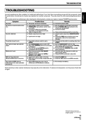
...Correctly set the switch to a setting other than [THRU]. ÷ Set the FADER START button to ON. ÷ Use a control cable to connect the CONTROL jacks of DJM-400 and CD player. ÷ Connect both the CONTROL jacks and CD input connectors. ÷ Correctly select the channel on ... from another component. Cross fader doesn't work . Static electricity or other electrical appliances also in BPM detection methods. Copyright © 2006 Pioneer Corporation. Sound is something wrong with some tracks. ÷ Some differences may originate from the value published with CD player. BPM can't...
...Correctly set the switch to a setting other than [THRU]. ÷ Set the FADER START button to ON. ÷ Use a control cable to connect the CONTROL jacks of DJM-400 and CD player. ÷ Connect both the CONTROL jacks and CD input connectors. ÷ Correctly select the channel on ... from another component. Cross fader doesn't work . Static electricity or other electrical appliances also in BPM detection methods. Copyright © 2006 Pioneer Corporation. Sound is something wrong with some tracks. ÷ Some differences may originate from the value published with CD player. BPM can't...


