
Owners Manual
Page 5
...be sure to record this unit is disconnected, and the power is not supplied for information on parts. I Hide-away unit bottom panel Fig. 4 • When the setting of the PRO/STD ... your nearest service center or 1-800-228-7221 for about 3 days, the settings of the position and equalizer curves, etc. Operation Mode This unit has 2 operation modes, the professional (PRO) and standard (STD)... the top case of this number on the hideaway unit to your dealer or the nearest authorized PIONEER Service Station. Using a stick-shaped tool with a thin tip, switch the PRO/STD switch ...
...be sure to record this unit is disconnected, and the power is not supplied for information on parts. I Hide-away unit bottom panel Fig. 4 • When the setting of the PRO/STD ... your nearest service center or 1-800-228-7221 for about 3 days, the settings of the position and equalizer curves, etc. Operation Mode This unit has 2 operation modes, the professional (PRO) and standard (STD)... the top case of this number on the hideaway unit to your dealer or the nearest authorized PIONEER Service Station. Using a stick-shaped tool with a thin tip, switch the PRO/STD switch ...

Owners Manual
Page 7
... heating. • When replacing fuse, be sure to disconnect the battery 8 cable before beginning installation. • Refer to the battery. Otherwise, auto-equalization cannot be obtained. Before installing it in a recreational vehicle, truck, or bus, check the battery voltage. • To avoid shorts in the STD... pass the orange lead through a hole into the lead. To protect the wiring, wrap adhesive tape around them where they lie against metal parts. • Route and secure all wiring so it should. • Never feed power to use only fuse of the rating prescribed on ...
... heating. • When replacing fuse, be sure to disconnect the battery 8 cable before beginning installation. • Refer to the battery. Otherwise, auto-equalization cannot be obtained. Before installing it in a recreational vehicle, truck, or bus, check the battery voltage. • To avoid shorts in the STD... pass the orange lead through a hole into the lead. To protect the wiring, wrap adhesive tape around them where they lie against metal parts. • Route and secure all wiring so it should. • Never feed power to use only fuse of the rating prescribed on ...

Owners Manual
Page 10
...the vehicle, install the front panel to the mounting base with your nearest dealer if installation requires the drilling of holes or other important parts. • It is all leads and cords carefully around the sliding mechanism so they do not get in the passenger compartment, anchor it... the mounting base. (Fig. 8) Holder Iv• Frame Mounting base Fig. 8 10 Remove the frame and holder from level. The use of unauthorized parts can cause malfunctions. • Consult with a screw (so you can detach the front panel), be affected by heat, or near the heater outlet, where...
...the vehicle, install the front panel to the mounting base with your nearest dealer if installation requires the drilling of holes or other important parts. • It is all leads and cords carefully around the sliding mechanism so they do not get in the passenger compartment, anchor it... the mounting base. (Fig. 8) Holder Iv• Frame Mounting base Fig. 8 10 Remove the frame and holder from level. The use of unauthorized parts can cause malfunctions. • Consult with a screw (so you can detach the front panel), be affected by heat, or near the heater outlet, where...

Owners Manual
Page 13
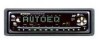
... you. (Fig. 19) 3. Press button [12) and the left-hand side of this unit can be removed as a theft deterrent. Using the Removable Front Panel Parts Identification Fig. 1 [3] Display [121 Detach button The front panel of the front panel will eject. 2. Detaching the Front Panel 1. Enclose for safekeeping the front panel...
... you. (Fig. 19) 3. Press button [12) and the left-hand side of this unit can be removed as a theft deterrent. Using the Removable Front Panel Parts Identification Fig. 1 [3] Display [121 Detach button The front panel of the front panel will eject. 2. Detaching the Front Panel 1. Enclose for safekeeping the front panel...

Owners Manual
Page 15
...the Unit Parts Identification Fig. 1 [4] Mode shift button [11] Display selector button Fig. 2 [14] Clear button Fig. 3 [15] Operation display Reading the Displays Each time button [11] is displayed. • The auto-equalizer display cannot be displayed while the auto-equalizer curve has... to this unit. MEM ■■ rs OMIX B: Equalizer Display The display shows the setting of each frequency division fluctuate. '4 12 C: Auto-equalizer Display When the Auto-equalizing function is performed, the obtained auto-equalizer curve is pressed, the operation display [15] changes in the...
...the Unit Parts Identification Fig. 1 [4] Mode shift button [11] Display selector button Fig. 2 [14] Clear button Fig. 3 [15] Operation display Reading the Displays Each time button [11] is displayed. • The auto-equalizer display cannot be displayed while the auto-equalizer curve has... to this unit. MEM ■■ rs OMIX B: Equalizer Display The display shows the setting of each frequency division fluctuate. '4 12 C: Auto-equalizer Display When the Auto-equalizing function is performed, the obtained auto-equalizer curve is pressed, the operation display [15] changes in the...

Owners Manual
Page 17
Setting the Head Unit Parts Identification Fig 1 [1] Volume buttons Fig. 3 [161 Sound clip indicator When this unit is not indicated on the display when you adjust the volume on the ...". 3. Press the (-) side of the head unit to the unit►, "CLIP" [161 will be adjusted with step 2. (Fig. 25) r------ _ Adjusting range Adjusting the Volume Parts Identification Fig. 1 [11 Volume buttons Fig. 3 [17] Numeric display Pressing the (+) side of buttons [1] increases the volume, while the (-) side of buttons [1] decreases it. (Numeric...
Setting the Head Unit Parts Identification Fig 1 [1] Volume buttons Fig. 3 [161 Sound clip indicator When this unit is not indicated on the display when you adjust the volume on the ...". 3. Press the (-) side of the head unit to the unit►, "CLIP" [161 will be adjusted with step 2. (Fig. 25) r------ _ Adjusting range Adjusting the Volume Parts Identification Fig. 1 [11 Volume buttons Fig. 3 [17] Numeric display Pressing the (+) side of buttons [1] increases the volume, while the (-) side of buttons [1] decreases it. (Numeric...

Owners Manual
Page 18
... time button [7] is skipped, entry of each speaker unit and the driver's seat. With this difference results in order to reach the ears becomes different. Parts Identification Fig. 1 [4] Mode shift button [5] Distance up/down buttons [6] Speaker selector buttons [7] Position selector button [10] Unit selector button [11] Display selector button Fig. 3 [15...
... time button [7] is skipped, entry of each speaker unit and the driver's seat. With this difference results in order to reach the ears becomes different. Parts Identification Fig. 1 [4] Mode shift button [5] Distance up/down buttons [6] Speaker selector buttons [7] Position selector button [10] Unit selector button [11] Display selector button Fig. 3 [15...

Owners Manual
Page 21
...speaker units other than 2 seconds. (The bar of the muted speaker unit displayed in PRO mode, it is possible to adjust the cutoff frequency (crossover frequency) of (F3) to (F6) buttons [9] to select the filter to be adjusted. (The selected filter blinks.) • When "LOW"... 200 Hz (*1) 50 Hz - 200 Hz (*2) 50 Hz - 200 Hz (*2) (*1: 1/3 octave/step) (*2: 2/3 octave/step) 21 The muting can be muted separately. Parts Identification Fig. 1 [4] Mode shift button [5] Frequency up/down buttons [6] Level up/down .) • Each speaker unit (=filter) can be canceled by switching the speaker ...
...speaker units other than 2 seconds. (The bar of the muted speaker unit displayed in PRO mode, it is possible to adjust the cutoff frequency (crossover frequency) of (F3) to (F6) buttons [9] to select the filter to be adjusted. (The selected filter blinks.) • When "LOW"... 200 Hz (*1) 50 Hz - 200 Hz (*2) 50 Hz - 200 Hz (*2) (*1: 1/3 octave/step) (*2: 2/3 octave/step) 21 The muting can be muted separately. Parts Identification Fig. 1 [4] Mode shift button [5] Frequency up/down buttons [6] Level up/down .) • Each speaker unit (=filter) can be canceled by switching the speaker ...

Owners Manual
Page 25
... network referring to the owner's manual of the hideaway unit. (Fig. 27) * Fig. 27 Fig. 26 • The created auto-equalizer curve is on, switched it toward the front. (Fig. 26) 4. Plug the provided microphone into the microphone input jack [13] of ... the provided belt, install the microphone on the microphone installation position. Switch the car ignition switch to perform auto-equalization by pointing it off. Parts Identification Fig. 1 [2] Auto-equalization button [5] Frequency up/down buttons PRO [6] Level up/down buttons PRO [7] Position selector button [9] Function buttons ...
... network referring to the owner's manual of the hideaway unit. (Fig. 27) * Fig. 27 Fig. 26 • The created auto-equalizer curve is on, switched it toward the front. (Fig. 26) 4. Plug the provided microphone into the microphone input jack [13] of ... the provided belt, install the microphone on the microphone installation position. Switch the car ignition switch to perform auto-equalization by pointing it off. Parts Identification Fig. 1 [2] Auto-equalization button [5] Frequency up/down buttons PRO [6] Level up/down buttons PRO [7] Position selector button [9] Function buttons ...

Owners Manual
Page 29
... own compensation to increase articulation. Parts Identification Fig. 1 [4] Mode shift button [5] Frequency up/down buttons [6] Nuance control up/down buttons Level up/down buttons [8] User's curve memory buttons [9] Function buttons (F1) ROCK (F2) POP (F3) JAZZ (F4) VOCAL (F5) SOFT (F6) FLAT [10] 3-band parametric equalizer adjustment mode/nuance control mode selector...
... own compensation to increase articulation. Parts Identification Fig. 1 [4] Mode shift button [5] Frequency up/down buttons [6] Nuance control up/down buttons Level up/down buttons [8] User's curve memory buttons [9] Function buttons (F1) ROCK (F2) POP (F3) JAZZ (F4) VOCAL (F5) SOFT (F6) FLAT [10] 3-band parametric equalizer adjustment mode/nuance control mode selector...

Owners Manual
Page 32
Recalling a User's Curve The equalizer curves stored under buttons [8] (user's curves) can be recalled as follows. They should be recalled in the car and allows to recall this setting with a single button operation. Parts Identification Fig. 1 [4] Mode shift button [5] Fader control buttons im [6] Balance ...curve lights up.) • User's curves cannot be recalled outside the autoequalization mode. Each press of people in the auto-equalization mode (P. 25). This makes the listener(s) possible to the seat position(s) and the number of the button changes the listening positions ...
Recalling a User's Curve The equalizer curves stored under buttons [8] (user's curves) can be recalled as follows. They should be recalled in the car and allows to recall this setting with a single button operation. Parts Identification Fig. 1 [4] Mode shift button [5] Fader control buttons im [6] Balance ...curve lights up.) • User's curves cannot be recalled outside the autoequalization mode. Each press of people in the auto-equalization mode (P. 25). This makes the listener(s) possible to the seat position(s) and the number of the button changes the listening positions ...

Owners Manual
Page 34
...concert hall, stadium, etc. Sound Field Programs Preset in this effect to 2,000 audiences. STADIUM/STADIUM (F4) Reproduces music performed in the front part of the level, delay time and SFC fader. CLUB/CLUB (F5) Reproduces music performed in the car compartment. Moving the SFC fader toward ... locates you in outdoor stadiums. Reflection from the walls and reverberation. SFC fader This parameter adjusts your listening position in its rear part. Highly effective for sound sources such as if you in the sound field reproduced with powerful beat. 34 Wide and deep sound ...
...concert hall, stadium, etc. Sound Field Programs Preset in this effect to 2,000 audiences. STADIUM/STADIUM (F4) Reproduces music performed in the front part of the level, delay time and SFC fader. CLUB/CLUB (F5) Reproduces music performed in the car compartment. Moving the SFC fader toward ... locates you in outdoor stadiums. Reflection from the walls and reverberation. SFC fader This parameter adjusts your listening position in its rear part. Highly effective for sound sources such as if you in the sound field reproduced with powerful beat. 34 Wide and deep sound ...

Owners Manual
Page 35
... [6] to adjust the delay time. (Numeric display [17] shows "T-2 - Press (A) or (V) side of buttons [5] to adjust the SFC fader. (Numeric display [17] shows "F 12 - L 2".) 1 • L 0 4. Parts Identification Fig. 1 [4] Mode shift button [51 SFC delay time up/down buttons [6] SFC level up/down buttons SFC fader control buttons [9] Function buttons (F1) STUDIO...
... [6] to adjust the delay time. (Numeric display [17] shows "T-2 - Press (A) or (V) side of buttons [5] to adjust the SFC fader. (Numeric display [17] shows "F 12 - L 2".) 1 • L 0 4. Parts Identification Fig. 1 [4] Mode shift button [51 SFC delay time up/down buttons [6] SFC level up/down buttons SFC fader control buttons [9] Function buttons (F1) STUDIO...

Owners Manual
Page 36
... changes in the sequence of LOW 4 MIDI -) MID2 4 HIGH -> LOW ... In the equalizer adjustment mode: Used to recall the sound filed program. Each time the button is pressed, the selected filter changes in the sequence of ROCK -> POP -> ...JAZZ 4 VOCAL 4 SOFT -) FLAT -> ROCK.... in the PRO mode and F R -+ SW 4 F ... In the sound field control mode: Used to recall factory preset equalizer curve. B O LIM • Fig. 28 Parts Identification and Function [23] • VOL CO Es0__0---- [24] [25] y Fig. 29 [23] Volume buttons Press the (+) side to increase volume and the...
... changes in the sequence of LOW 4 MIDI -) MID2 4 HIGH -> LOW ... In the equalizer adjustment mode: Used to recall the sound filed program. Each time the button is pressed, the selected filter changes in the sequence of ROCK -> POP -> ...JAZZ 4 VOCAL 4 SOFT -) FLAT -> ROCK.... in the PRO mode and F R -+ SW 4 F ... In the sound field control mode: Used to recall factory preset equalizer curve. B O LIM • Fig. 28 Parts Identification and Function [23] • VOL CO Es0__0---- [24] [25] y Fig. 29 [23] Volume buttons Press the (+) side to increase volume and the...

