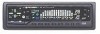
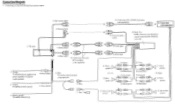
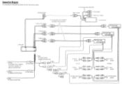
Pioneer DEQ 7600 Diagram - Equalizer Crossover
Pioneer DEQ 7600 Diagram
Related Manual Pages
Similar Questions

Need Wiring Diagram For Deq-7600 Eq
(Posted by loridelcerro 11 years ago)
Find free Pioneer DEQ 7600 - Equalizer / Crossover manuals and user guides available at ManualOwl.com. Try out our unique manual viewer allowing you to interact with manuals from directly within your browser!
View thousands of Pioneer DEQ 7600 - Equalizer / Crossover user reviews and customer ratings available at ReviewOwl.com.
Complete Pioneer customer service contact information including steps to reach representatives, hours of operation, customer support links and more from ContactHelp.com.
See detailed Pioneer customer service rankings, employee comments and much more from our sister site.