Manual
Page 2
Installation 4 Installing the Unit 4 • Mounting with Brackets • Mounting with Velcro Tape Installing the Remote Control Unit ...... 5 Fitting the Remote Control Unit 5 Installation Using Only the Mounting Base ....... 5 Installation Using the Mounting Base and the Bracket 6 Connecting the Units 8 Connecting to a Sold Separately Power Amp .... 9 Connecting the System (A 10 Connecting the System (B 11 Speaker Input Jack Connection 12 VIDEO Input/Output Connection 13 Connection Diagram 14 Connecting the Power Cord 14 Key Finder 16 • Remote Controller Before Using ...
Installation 4 Installing the Unit 4 • Mounting with Brackets • Mounting with Velcro Tape Installing the Remote Control Unit ...... 5 Fitting the Remote Control Unit 5 Installation Using Only the Mounting Base ....... 5 Installation Using the Mounting Base and the Bracket 6 Connecting the Units 8 Connecting to a Sold Separately Power Amp .... 9 Connecting the System (A 10 Connecting the System (B 11 Speaker Input Jack Connection 12 VIDEO Input/Output Connection 13 Connection Diagram 14 Connecting the Power Cord 14 Key Finder 16 • Remote Controller Before Using ...

Manual
Page 3
Using Multi-CD Players 41 Repeat Modes (PLAY MODE 41 Pause (PAUSE 42 Random Play (RANDOM 43 Scan Play (SCAN 43 CD Sound Quality Adjustment (COMP SELECT 45 • COMP/DBE ON/OFF Switching ITS (Instant Track Selection 45 • ITS Programming (ITS INPUT) • ITS Play (ITS PLAY) • Erase a Track Program • Erase a Disc Program Disc Title 48 • Disc Title Input (TITLE INPUT) CD TEXT Function (for CD TEXT compatible type 50 • Title Display Switching • Title Scroll Other Functions 52 • Switching the Multi-CD Player • Playing Discs on a 50-Disc...
Using Multi-CD Players 41 Repeat Modes (PLAY MODE 41 Pause (PAUSE 42 Random Play (RANDOM 43 Scan Play (SCAN 43 CD Sound Quality Adjustment (COMP SELECT 45 • COMP/DBE ON/OFF Switching ITS (Instant Track Selection 45 • ITS Programming (ITS INPUT) • ITS Play (ITS PLAY) • Erase a Track Program • Erase a Disc Program Disc Title 48 • Disc Title Input (TITLE INPUT) CD TEXT Function (for CD TEXT compatible type 50 • Title Display Switching • Title Scroll Other Functions 52 • Switching the Multi-CD Player • Playing Discs on a 50-Disc...

Manual
Page 4
Installing the Unit Mounting with Brackets Mounting with your nearest dealer if installation requires the drilling of the leads are trapped between this unit and the surrounding metalwork or fittings. • Do not mount this unit near the heater outlet, where it would be affected by heat, or near the doors, where rainwater might splash onto it does not break free while the car is moving, and cause injury or an accident. • If this unit is installed in the mechanism and cause a short circuit. Route all leads and cords carefully around the sliding mechanism so they do not ...
Installing the Unit Mounting with Brackets Mounting with your nearest dealer if installation requires the drilling of the leads are trapped between this unit and the surrounding metalwork or fittings. • Do not mount this unit near the heater outlet, where it would be affected by heat, or near the doors, where rainwater might splash onto it does not break free while the car is moving, and cause injury or an accident. • If this unit is installed in the mechanism and cause a short circuit. Route all leads and cords carefully around the sliding mechanism so they do not ...

Manual
Page 5
Passenger seat Mounting Base Double-sided tape Not used Used Fitting horizontally Fitting vertically Installation Using Only the Mounting Base • To avoid it clicks into place. Fitting the Remote Control Unit • Press the remote controller unit onto the mounting base until it being a hindrance to driving, always install the remote control unit to be attached. not the driver's side. • Before using double-sided tape, clean off any dirt on the surface to which the doublesided tape is slanting upwards at an angle when fitted. • Install the mounting base so that...
Passenger seat Mounting Base Double-sided tape Not used Used Fitting horizontally Fitting vertically Installation Using Only the Mounting Base • To avoid it clicks into place. Fitting the Remote Control Unit • Press the remote controller unit onto the mounting base until it being a hindrance to driving, always install the remote control unit to be attached. not the driver's side. • Before using double-sided tape, clean off any dirt on the surface to which the doublesided tape is slanting upwards at an angle when fitted. • Install the mounting base so that...

Manual
Page 6
Screws (3 10 mm) Bracket Mounting base not the driver's side. Method A This example is for when the console is wide enough to the passenger's side - Method B This example is for when the console is not wide enough to have installation space for the mounting base. • Install the mounting base in such a way that it being a hindrance to driving, always install the remote control unit to have installation space for the mounting base. Installation Using the Mounting Base and the Bracket • To avoid it will not hit the seat when the seat is adjusted.
Screws (3 10 mm) Bracket Mounting base not the driver's side. Method A This example is for when the console is wide enough to the passenger's side - Method B This example is for when the console is not wide enough to have installation space for the mounting base. • Install the mounting base in such a way that it being a hindrance to driving, always install the remote control unit to have installation space for the mounting base. Installation Using the Mounting Base and the Bracket • To avoid it will not hit the seat when the seat is adjusted.

Manual
Page 7
Passenger seat • • Before drilling any mounting holes, confirm that the screws will not interfere with any dirt on the surface to which the doublesided tape is to be attached. • • Before using double-sided tape, clean off any of the cars operating systems (such as the fuel line, brake lines, electrical wiring, etc.). Passenger seat Double-sided tape Drill holes 2 - 2.5 mm in diameter Screws (4 12 mm)
Passenger seat • • Before drilling any mounting holes, confirm that the screws will not interfere with any dirt on the surface to which the doublesided tape is to be attached. • • Before using double-sided tape, clean off any of the cars operating systems (such as the fuel line, brake lines, electrical wiring, etc.). Passenger seat Double-sided tape Drill holes 2 - 2.5 mm in diameter Screws (4 12 mm)
Manual
Page 8
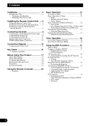
If the insulation of the wiring melts or gets torn, there is a danger of the lead will damage the lead insulation and cause a very dangerous short. • Do not shorten any moving parts, such as near the heater outlet. If you do not connect the blue/white lead to the products or fire. The current capacity of the wiring short-circuiting to the vehicle body. • Don't pass the yellow lead through a hole into the lead. Such connection could cause excessive current drain and malfunction. • To prevent incorrect connection, the input side of the auto-antenna. Please ground this...
If the insulation of the wiring melts or gets torn, there is a danger of the lead will damage the lead insulation and cause a very dangerous short. • Do not shorten any moving parts, such as near the heater outlet. If you do not connect the blue/white lead to the products or fire. The current capacity of the wiring short-circuiting to the vehicle body. • Don't pass the yellow lead through a hole into the lead. Such connection could cause excessive current drain and malfunction. • To prevent incorrect connection, the input side of the auto-antenna. Please ground this...

Manual
Page 9
Connecting to a Sold Separately Power Amp This product can be connected to a sold separately power amp using a different amp (sold separately) System remote control System remote control System remote control Front speaker Front speaker Rear speaker Subwoofer Perform these connections when using the RCA output jacks. Rear speaker Subwoofer This Product Rear output Front output Subwoofer output RCA cable (sold separately) Blue/white To system control terminal of the power amp or Auto-antenna relay control terminal. (Max. 300 mA 12 V DC) Power amp (sold separately) Power amp (...
Connecting to a Sold Separately Power Amp This product can be connected to a sold separately power amp using a different amp (sold separately) System remote control System remote control System remote control Front speaker Front speaker Rear speaker Subwoofer Perform these connections when using the RCA output jacks. Rear speaker Subwoofer This Product Rear output Front output Subwoofer output RCA cable (sold separately) Blue/white To system control terminal of the power amp or Auto-antenna relay control terminal. (Max. 300 mA 12 V DC) Power amp (sold separately) Power amp (...

Manual
Page 10
Display with an IP-BUS cable (sold separately) Black Multi-CD player Blue (sold separately) Red RGB cable (supplied with the TV tuner) Hide-away TV Tuner (sold separately) Speaker Unit (supplied with the display) Gray Connecting the System (A) Green Navigation System (sold separately) Gray Green This Product Yellow/black To yellow/black lead (GUIDE ON) on the navigation system RGB cable (supplied) Gray V.SEL cable (supplied with the display) Green RCA cable (sold separately) Green Gray Green RGB cable (supplied with the display) There is no need to connect a display ...
Display with an IP-BUS cable (sold separately) Black Multi-CD player Blue (sold separately) Red RGB cable (supplied with the TV tuner) Hide-away TV Tuner (sold separately) Speaker Unit (supplied with the display) Gray Connecting the System (A) Green Navigation System (sold separately) Gray Green This Product Yellow/black To yellow/black lead (GUIDE ON) on the navigation system RGB cable (supplied) Gray V.SEL cable (supplied with the display) Green RCA cable (sold separately) Green Gray Green RGB cable (supplied with the display) There is no need to connect a display ...

Manual
Page 11
Display with an IP-BUS cable (sold separately) Green Multi-CD player (sold separately) Yellow/black To yellow/black lead (GUIDE ON) on the navigation system Gray Green This Product RGB cable (supplied) V.SEL cable (supplied with the display) Gray There is no need to connect a display that does Blue not feature an IP-BUS cable in the same way as in *1. Speaker Unit (supplied with the display) Blue IP-BUS cable (supplied) Blue IP-BUS cable (supplied with the display) Black Connect a display that does not feature these jacks or a cable. Connecting the System (B) Green ...
Display with an IP-BUS cable (sold separately) Green Multi-CD player (sold separately) Yellow/black To yellow/black lead (GUIDE ON) on the navigation system Gray Green This Product RGB cable (supplied) V.SEL cable (supplied with the display) Gray There is no need to connect a display that does Blue not feature an IP-BUS cable in the same way as in *1. Speaker Unit (supplied with the display) Blue IP-BUS cable (supplied) Blue IP-BUS cable (supplied with the display) Black Connect a display that does not feature these jacks or a cable. Connecting the System (B) Green ...

Manual
Page 12
This product Speaker input terminal Gray Gray/black White White/black Car stereo with speaker output jacks. Right Front speaker Left Speaker Input Jack Connection This product also be connected to a car stereo without RCA output jacks by using the speaker input jacks.
This product Speaker input terminal Gray Gray/black White White/black Car stereo with speaker output jacks. Right Front speaker Left Speaker Input Jack Connection This product also be connected to a car stereo without RCA output jacks by using the speaker input jacks.

Manual
Page 13
Yellow Left (White) Right (Red) This product Display with RCA input jacks to the video inputs A and B on this product. VIDEO Input/Output Connection It is possible to use up to two external video components by connecting them to Rear Display output, you can also watch the external video component's picture. When connecting the Display with RCA input jacks To audio inputs To video input VIDEO input A, VIDEO input B RCA cables (sold separately) Rear display output Right (Red) Left (White) Yellow To audio outputs To video output RCA cables (sold separately) External video component ...
Yellow Left (White) Right (Red) This product Display with RCA input jacks to the video inputs A and B on this product. VIDEO Input/Output Connection It is possible to use up to two external video components by connecting them to Rear Display output, you can also watch the external video component's picture. When connecting the Display with RCA input jacks To audio inputs To video input VIDEO input A, VIDEO input B RCA cables (sold separately) Rear display output Right (Red) Left (White) Yellow To audio outputs To video output RCA cables (sold separately) External video component ...
Manual
Page 14
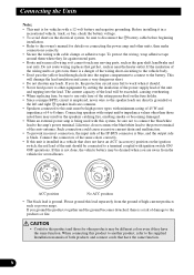
This lead must be connected to detect the ON/OFF status of the parking brake. Yellow To terminal always supplied with needle-nosed pliers. • The position of the parking brake switch depends on the cellular telephone. If not, keep the Audio Mute lead free of ignition switch position. For details, consult the vehicle owner's manual. Yellow/black If you use a cellular telephone, connect it via the Audio Mute lead on the vehicle model. Black (ground) To vehicle (metal) body. Fuse resistor Connection method Ground side Clamp the parking brake switch power supply side lead. ...
This lead must be connected to detect the ON/OFF status of the parking brake. Yellow To terminal always supplied with needle-nosed pliers. • The position of the parking brake switch depends on the cellular telephone. If not, keep the Audio Mute lead free of ignition switch position. For details, consult the vehicle owner's manual. Yellow/black If you use a cellular telephone, connect it via the Audio Mute lead on the vehicle model. Black (ground) To vehicle (metal) body. Fuse resistor Connection method Ground side Clamp the parking brake switch power supply side lead. ...

Manual
Page 15
This product Antenna jack Antenna extension cable (supplied) If the antenna from the vehicle does not reach the Antenna jack, use this cable. Blue/white To system control terminal of the power amp or Auto-antenna relay control terminal. (Max. 300 mA 12 V DC) Front speaker Left Rear speaker White Gray White/ black Green Gray/black Left (White) Green/ black Violet/black With a 2 speaker system, do not connect anything to the speaker leads that are not connected to speakers. Front speaker Right Rear speaker
This product Antenna jack Antenna extension cable (supplied) If the antenna from the vehicle does not reach the Antenna jack, use this cable. Blue/white To system control terminal of the power amp or Auto-antenna relay control terminal. (Max. 300 mA 12 V DC) Front speaker Left Rear speaker White Gray White/ black Green Gray/black Left (White) Green/ black Violet/black With a 2 speaker system, do not connect anything to the speaker leads that are not connected to speakers. Front speaker Right Rear speaker

Manual
Page 16
Remote Controller V.SEL button button AUDIO button TA button DISPLAY button ATT button Buttons 1- 6 +/- button SOURCE button button BAND button FUNCTION button MENU button PTY button PGM button
Remote Controller V.SEL button button AUDIO button TA button DISPLAY button ATT button Buttons 1- 6 +/- button SOURCE button button BAND button FUNCTION button MENU button PTY button PGM button

Manual
Page 17
It is lit, you can use the buttons or buttons to switch selection options of the , FUNCTION and AUDIO buttons you 're in Western Europe, Asia, the Middle East, Africa and Oceania. About This Product • This product complies with the buttons. • When "SEL" is not a malfunction. Key Guidance Indicators eg: Function Menu eg: Audio Menu • When "ON" and "OFF" are selected, the selected setting will be displayed in yellow. • The image sometimes fluctuates. The RDS function operates only in improper reception. This product's display features Key Guidance ...
It is lit, you can use the buttons or buttons to switch selection options of the , FUNCTION and AUDIO buttons you 're in Western Europe, Asia, the Middle East, Africa and Oceania. About This Product • This product complies with the buttons. • When "SEL" is not a malfunction. Key Guidance Indicators eg: Function Menu eg: Audio Menu • When "ON" and "OFF" are selected, the selected setting will be displayed in yellow. • The image sometimes fluctuates. The RDS function operates only in improper reception. This product's display features Key Guidance ...
Manual
Page 18
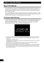
It is especially important that you begin using this product. The ignition is pressed. The ignition switch is intended to help you benefit fully from their operation by reading through the manual before you read and observe the "Precaution" on the display. This operation manual is turned to the ACC position, and the engine started in other sections. To Ensure Safe Driving To ensure safe vehicle operation, complicated functions are selected while driving, "YOU CANNOT USE THIS FUNCTION WHILE DRIVING" is set to the OFF or ACC position, the condition of the parking brake cannot be ...
It is especially important that you begin using this product. The ignition is pressed. The ignition switch is intended to help you benefit fully from their operation by reading through the manual before you read and observe the "Precaution" on the display. This operation manual is turned to the ACC position, and the engine started in other sections. To Ensure Safe Driving To ensure safe vehicle operation, complicated functions are selected while driving, "YOU CANNOT USE THIS FUNCTION WHILE DRIVING" is set to the OFF or ACC position, the condition of the parking brake cannot be ...
Manual
Page 19
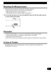
... of Trouble Should this product for the first time after installation. • When the machine fails to operate properly, contact your dealer or nearest authorized PIONEER Service Station. Precaution • Keep this manual handy as a reference for operating procedures and precautions. • Always keep the volume low enough for outside sounds...
... of Trouble Should this product for the first time after installation. • When the machine fails to operate properly, contact your dealer or nearest authorized PIONEER Service Station. Precaution • Keep this manual handy as a reference for operating procedures and precautions. • Always keep the volume low enough for outside sounds...

Manual
Page 20
This product is not in use, attach it may become jammed under the brake or accelerator pedal. Batteries • Use only AAA or IEC R03 1.5 V batteries. • Remove the batteries if the remote controller is not used for a month or longer. • Do not attempt to recharge the supplied batteries. • Do not mix new and used batteries. • In the event of the signal reception on the color display (sold separately) to operate. • When the controller is equipped with a remote controller for convenient operation. • Point the controller in direct sunlight. • Do ...
This product is not in use, attach it may become jammed under the brake or accelerator pedal. Batteries • Use only AAA or IEC R03 1.5 V batteries. • Remove the batteries if the remote controller is not used for a month or longer. • Do not attempt to recharge the supplied batteries. • Do not mix new and used batteries. • In the event of the signal reception on the color display (sold separately) to operate. • When the controller is equipped with a remote controller for convenient operation. • Point the controller in direct sunlight. • Do ...

Manual
Page 21
CD player (one disc only) TV VIDEO A VIDEO B Tuner DAB (Digital Audio Broadcasting) Multi-CD player AUX Speaker Input • In the following explains the initial operations required before you can listen to pages 65 and 66.) Each press changes the Source ... To Listen to Music The following cases, the sound source will not change: * When the sound source from another product is not connected to this product. * When no magazine is set in the Multi-CD player. * When no disc is set in the CD player. * When the AUX (external input), VIDEO A, VIDEO B and Speaker Input are set to OFF. (Refer to...
CD player (one disc only) TV VIDEO A VIDEO B Tuner DAB (Digital Audio Broadcasting) Multi-CD player AUX Speaker Input • In the following explains the initial operations required before you can listen to pages 65 and 66.) Each press changes the Source ... To Listen to Music The following cases, the sound source will not change: * When the sound source from another product is not connected to this product. * When no magazine is set in the Multi-CD player. * When no disc is set in the CD player. * When the AUX (external input), VIDEO A, VIDEO B and Speaker Input are set to OFF. (Refer to...