Service Manual
Page 1
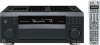
.../MD TUNER VIDEO2 MASTER VOLUME VSX-52TX AUDIO/VIDEO MULTI-CHANNEL RECEIVER VSX-52TX VSX-1014TX-K ORDER NO. PIONEER CORPORATION 4-1, Meguro 1-chome, Meguro-ku, Tokyo 153-8654, Japan PIONEER ELECTRONICS (USA) INC. Box 1760, Long Beach, CA 90801-1760, U.S.A. PIONEER EUROPE NV Haven 1087, Keetberglaan 1, 9120 Melsele, Belgium PIONEER ELECTRONICS ASIACENTRE PTE. P.O. RRV2977 THIS MANUAL IS APPLICABLE TO THE FOLLOWING...
.../MD TUNER VIDEO2 MASTER VOLUME VSX-52TX AUDIO/VIDEO MULTI-CHANNEL RECEIVER VSX-52TX VSX-1014TX-K ORDER NO. PIONEER CORPORATION 4-1, Meguro 1-chome, Meguro-ku, Tokyo 153-8654, Japan PIONEER ELECTRONICS (USA) INC. Box 1760, Long Beach, CA 90801-1760, U.S.A. PIONEER EUROPE NV Haven 1087, Keetberglaan 1, 9120 Melsele, Belgium PIONEER ELECTRONICS ASIACENTRE PTE. P.O. RRV2977 THIS MANUAL IS APPLICABLE TO THE FOLLOWING...

Service Manual
Page 2
.../or parts must not exceed 0.5 mA. These are not qualified to time. For the latest information, always consult the current PIONEER Service Manual. F 2 VSX-52TX 1 2 3 4 WARNING B This product contains lead in this manual. Any current measured must be obtained at a nominal charge from time to perform the repair of the appliance (input/output terminals...
.../or parts must not exceed 0.5 mA. These are not qualified to time. For the latest information, always consult the current PIONEER Service Manual. F 2 VSX-52TX 1 2 3 4 WARNING B This product contains lead in this manual. Any current measured must be obtained at a nominal charge from time to perform the repair of the appliance (input/output terminals...
Service Manual
Page 3
...54 3.17 REGULATOR ASSY ...56 3.18 TRANS 2-1, TRANS 2-2, DIODE, VH TR and SP/PS ASSYS 58 VSX-52TX 5 6 7 8 D E F 3 5 6 7 8 [ Important symbols for good services ] In this manual, be sure to apply the prescribed grease or glue to proper portions by following the instructions in accordance with... the procedures or instructions described in this manual, adjustments should be performed. 3. Shipping mode and shipping screws To protect the product from damages or failures that adjustments,...
...54 3.17 REGULATOR ASSY ...56 3.18 TRANS 2-1, TRANS 2-2, DIODE, VH TR and SP/PS ASSYS 58 VSX-52TX 5 6 7 8 D E F 3 5 6 7 8 [ Important symbols for good services ] In this manual, be sure to apply the prescribed grease or glue to proper portions by following the instructions in accordance with... the procedures or instructions described in this manual, adjustments should be performed. 3. Shipping mode and shipping screws To protect the product from damages or failures that adjustments,...
Service Manual
Page 6
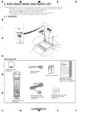
... Master Spare Parts List. The mark found on product are not in this manual. (In the case of the part. A Therefore, when replacing, be sure...VOL INPUT SELECT TV CH VOL DTVON/OFF REC DTVINFO MUTE TUNER DISPLAY REC STOP MPX AUDIO THX CH RETURN SUBTITLE HDD DVD CH CH RECEIVER CONTROL ...SELECT LOUDNESS SHIFT EFFECT /CH SEL SLEEP DIALOG E RECEIVER Remote Control Unit ( AXD7381 ) 8 9 1 10 12 14 15 13 16 AUDIO/VIDEO MULTI-CHANNEL RECEIVER VSX-52TX FM Wire Antenna (ADH7030) "AA" IEC LR6 batteries Operating Instructions Operating Instructions (VSX-52TX : ARB7302) (VSX-1014TX...
... Master Spare Parts List. The mark found on product are not in this manual. (In the case of the part. A Therefore, when replacing, be sure...VOL INPUT SELECT TV CH VOL DTVON/OFF REC DTVINFO MUTE TUNER DISPLAY REC STOP MPX AUDIO THX CH RETURN SUBTITLE HDD DVD CH CH RECEIVER CONTROL ...SELECT LOUDNESS SHIFT EFFECT /CH SEL SLEEP DIALOG E RECEIVER Remote Control Unit ( AXD7381 ) 8 9 1 10 12 14 15 13 16 AUDIO/VIDEO MULTI-CHANNEL RECEIVER VSX-52TX FM Wire Antenna (ADH7030) "AA" IEC LR6 batteries Operating Instructions Operating Instructions (VSX-52TX : ARB7302) (VSX-1014TX...
Service Manual
Page 117
...disables failure diagnosis of thermistor, and its resistance is approx. 100 ohms at normal room temperature. 4 The unit turns itself off . E 4 TRANS 2-1 Assy F VSX-52TX 117 5 6 7 8 B 3 "OVERHEAT" is powered. Note: A posistor is a kind of these Assys while the unit is displayed on the FL display...goes into state 1 above. Note: Use this unit, the large Heat Sink Block obstructs access to diagnose the Amplifier Section" in the service manual. If the Heat Sink Block is displayed on the FL display under normal temperature). 5 6 7 8 7.1.3 HOW TO DIAGNOSE THE UNIT WITH...
...disables failure diagnosis of thermistor, and its resistance is approx. 100 ohms at normal room temperature. 4 The unit turns itself off . E 4 TRANS 2-1 Assy F VSX-52TX 117 5 6 7 8 B 3 "OVERHEAT" is powered. Note: A posistor is a kind of these Assys while the unit is displayed on the FL display...goes into state 1 above. Note: Use this unit, the large Heat Sink Block obstructs access to diagnose the Amplifier Section" in the service manual. If the Heat Sink Block is displayed on the FL display under normal temperature). 5 6 7 8 7.1.3 HOW TO DIAGNOSE THE UNIT WITH...

Service Manual
Page 120
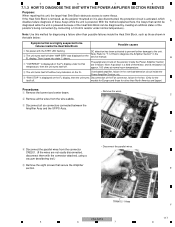
... seven connectors. 5 Disconnect the two flexible cables. 6 Remove the heatsink section. 1 2 3 4 7.1.4 DISASSEMBLY Note: Even if the unit shown in the photos and illustrations in this manual may differ from your product, the procedures described here are common. B C 3 ×2 3 ×2 2 4 ×7 5 6 2 5 3 ×2 Front side 3 ×2 D S POWER AMP-L Assy T POSI 1 L Assy E Q POWER AMP...
... seven connectors. 5 Disconnect the two flexible cables. 6 Remove the heatsink section. 1 2 3 4 7.1.4 DISASSEMBLY Note: Even if the unit shown in the photos and illustrations in this manual may differ from your product, the procedures described here are common. B C 3 ×2 3 ×2 2 4 ×7 5 6 2 5 3 ×2 Front side 3 ×2 D S POWER AMP-L Assy T POSI 1 L Assy E Q POWER AMP...


