

Owner's Manual
Page 1
A Hobbymatic 800., 801, 802, 803, 806, 807 instruction book
A Hobbymatic 800., 801, 802, 803, 806, 807 instruction book
Owner's Manual
Page 2
... the sewing mechanism Bobbin winding Inserting the bobbin Inserting the bobbin case Upper threading Threadingtheneedle Drawing up the bobbin thread Presser bar lifter Thread cutter Regulating the stitch length Sewing straight stitches Zigzag stitches Needle position Selecting utility stitches, 802 to 807 Selecting stretch stitches, 806 and 807 Utility stitches, models 802 to 807 Stretch stitches, models 806, 807 Thread tensions Changing the needle Reverse sewing Dropping the machine feed Changing the sewing foot Sewing feet Special sewing feet Buttonhole settings Sewing buttonholes Fitting...
... the sewing mechanism Bobbin winding Inserting the bobbin Inserting the bobbin case Upper threading Threadingtheneedle Drawing up the bobbin thread Presser bar lifter Thread cutter Regulating the stitch length Sewing straight stitches Zigzag stitches Needle position Selecting utility stitches, 802 to 807 Selecting stretch stitches, 806 and 807 Utility stitches, models 802 to 807 Stretch stitches, models 806, 807 Thread tensions Changing the needle Reverse sewing Dropping the machine feed Changing the sewing foot Sewing feet Special sewing feet Buttonhole settings Sewing buttonholes Fitting...
Owner's Manual
Page 4
... a while. and stretch-stitch selector dial (802-807) 6 Buttonhole and needle positioning lever 7 Spool pins 8 Bobbin winder 9 Hand wheel 10 Stop motion knob 11 Stitch length control 12 Reverse feed control 13 Base (on portable machines) 14 Needle plate 15 Bed cover 16 Sewing foot holder with sewing foot 17 Sewing foot retaining screw 18 Presser bar with the coloured markings identifying the terminals in the sewing lamp. The wires in this appliance may not correspond with thread cutter 19 Needle thread tension 20 Presser bar lifter (on the needle during sewing.
... a while. and stretch-stitch selector dial (802-807) 6 Buttonhole and needle positioning lever 7 Spool pins 8 Bobbin winder 9 Hand wheel 10 Stop motion knob 11 Stitch length control 12 Reverse feed control 13 Base (on portable machines) 14 Needle plate 15 Bed cover 16 Sewing foot holder with sewing foot 17 Sewing foot retaining screw 18 Presser bar with the coloured markings identifying the terminals in the sewing lamp. The wires in this appliance may not correspond with thread cutter 19 Needle thread tension 20 Presser bar lifter (on the needle during sewing.
Owner's Manual
Page 5
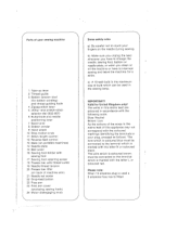
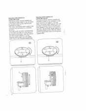
On models 800, 802 and 806 place it on the bed plate, and on both sides of the hinge catches properly in its original position. Before putting the machine away after sewing replace the receptacle in the slot. J 1 To replace the cover, reverse this receptacle from the machine for sewing. Removing the carrying case cover Open the hinges on models 801, 803 and 807 push it into the free arm. 7 -/ 800,802,806 4/- Foot control receptacle Remove this proce dure, making sure the bottom of the cover (G), move them back up (H) and then remove the cover (I).
On models 800, 802 and 806 place it on the bed plate, and on both sides of the hinge catches properly in its original position. Before putting the machine away after sewing replace the receptacle in the slot. J 1 To replace the cover, reverse this receptacle from the machine for sewing. Removing the carrying case cover Open the hinges on models 801, 803 and 807 push it into the free arm. 7 -/ 800,802,806 4/- Foot control receptacle Remove this proce dure, making sure the bottom of the cover (G), move them back up (H) and then remove the cover (I).
Owner's Manual
Page 6
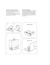
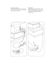
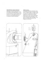
The machine starts sewing. Your machine is now ready for sewing. Foot control Place the foot control on the floor under the table. The more you press down with your foot. Electrical connection Push plug G into the machine socket and plug H into the wall socket. Press it down the pedal, the faster the machine runs. 2
The machine starts sewing. Your machine is now ready for sewing. Foot control Place the foot control on the floor under the table. The more you press down with your foot. Electrical connection Push plug G into the machine socket and plug H into the wall socket. Press it down the pedal, the faster the machine runs. 2
Owner's Manual
Page 8
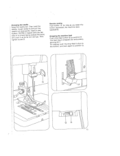
... pins 7 and place a spool of them. Pass the thread from the spooi around bobbin tension stud 3, wind it around the bobbin a few times and push the bobbin to the left and remove it to the right for winding. Place a bobbin on one of thread on bobbin winder 8 so that pin H enters slot G. Bobbin winding Disengage the sewing mechanism. Re engage the mechanism. 4 Disengaging the sewing mechanism Before you . When the bobbin...
... pins 7 and place a spool of them. Pass the thread from the spooi around bobbin tension stud 3, wind it around the bobbin a few times and push the bobbin to the left and remove it to the right for winding. Place a bobbin on one of thread on bobbin winder 8 so that pin H enters slot G. Bobbin winding Disengage the sewing mechanism. Re engage the mechanism. 4 Disengaging the sewing mechanism Before you . When the bobbin...

Owner's Manual
Page 9
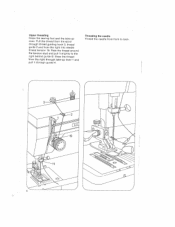
Inserting the bobbin case Pull up latch I . Release the latch. Stud G and latch I must point upwards. Cutout H must be flush. 5 Inserting the bobbin Insert the filled bobbin in the bobbin case so that the thread unreels towards the back (G). Then draw the thread into slot H and under the spring into eye I and push the bobbin case onto stud B as far as it will go.
Inserting the bobbin case Pull up latch I . Release the latch. Stud G and latch I must point upwards. Cutout H must be flush. 5 Inserting the bobbin Insert the filled bobbin in the bobbin case so that the thread unreels towards the back (G). Then draw the thread into slot H and under the spring into eye I and push the bobbin case onto stud B as far as it will go.
Owner's Manual
Page 10
Upper threading Raise the sewing foot and the take -up lever. Pass the thread around the tension stud and pull it through guide H. Threading the needle Thread the needle from the spool through take -up lever 1 and pull it slightly to back. 6 Draw the thread from the right through thread guiding hook 3, thread guide 2 and from the right into needle thread tension 19. Pull the thread from front to the right behind guide G.
Upper threading Raise the sewing foot and the take -up lever. Pass the thread around the tension stud and pull it through guide H. Threading the needle Thread the needle from the spool through take -up lever 1 and pull it slightly to back. 6 Draw the thread from the right through thread guiding hook 3, thread guide 2 and from the right into needle thread tension 19. Pull the thread from front to the right behind guide G.
Owner's Manual
Page 11
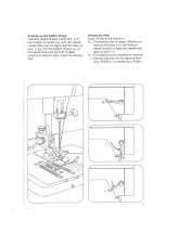
... by a notch. 7- Drawing up . Presser bar litter Lever 20 has three positions. Pull the bobbin thread out of the needle hole and lay both threads toward you remove the work, turn the balance wheel forward to raise the needle and take -up lever is lowered for sewing. = Darning position for the darning foot only. Turn hand wheel 9 toward the left and back under the sewing foot. Position I 7 G = The sewing foot is raised. (Before you...
... by a notch. 7- Drawing up . Presser bar litter Lever 20 has three positions. Pull the bobbin thread out of the needle hole and lay both threads toward you remove the work, turn the balance wheel forward to raise the needle and take -up lever is lowered for sewing. = Darning position for the darning foot only. Turn hand wheel 9 toward the left and back under the sewing foot. Position I 7 G = The sewing foot is raised. (Before you...
Owner's Manual
Page 12
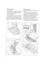
tPhthueellpbtrhaeecskswe. H shows how to cut them. The numbers indicate the length in mm. N 7 \ 8 Regulating the stitch length The stitch length is an oblique slot lRoofacitashteeedtmheaatcsthehiwenienbgatocwfkoaoortfd. Fig. roDrbkraarwo.utthe threads into the cutter slot and pull them downwards to set at mark G on models 806 and 807. /- Thread cutter (G) The thread cutter is set the stitch length control for sewing stretch stitches on the stitch length control.
tPhthueellpbtrhaeecskswe. H shows how to cut them. The numbers indicate the length in mm. N 7 \ 8 Regulating the stitch length The stitch length is an oblique slot lRoofacitashteeedtmheaatcsthehiwenienbgatocwfkoaoortfd. Fig. roDrbkraarwo.utthe threads into the cutter slot and pull them downwards to set at mark G on models 806 and 807. /- Thread cutter (G) The thread cutter is set the stitch length control for sewing stretch stitches on the stitch length control.
Owner's Manual
Page 14
...(se1ndsl.ttageepohttsTeceohetttushhocFsrsseetnritiegoibtdl.brrctleeiheohbacoqetletfatuoyloruoitroemrhnweueatdi)tl, zigzag-width. 7 10 Selecting utility stitches on models 802 to 807 The various utility indicated by black of the stitch panel stitches possible are letters in a selector dial clockwise dTttSsrohieutereiqretttnhccucshteiutidrioetitsloancdetlhiu.vtstc5etlrhaieutttncnoyghttohittluhheletewhsnbeegoraletntehltqteco,uttmitioasernrerid(dn1sc1eottzhehritgereoFezcszitaghpeiq.geno-zbwtnaredeigldio-ntowhgf.). Selecting stretch stitches on page 11.
...(se1ndsl.ttageepohttsTeceohetttushhocFsrsseetnritiegoibtdl.brrctleeiheohbacoqetletfatuoyloruoitroemrhnweueatdi)tl, zigzag-width. 7 10 Selecting utility stitches on models 802 to 807 The various utility indicated by black of the stitch panel stitches possible are letters in a selector dial clockwise dTttSsrohieutereiqretttnhccucshteiutidrioetitsloancdetlhiu.vtstc5etlrhaieutttncnoyghttohittluhheletewhsnbeegoraletntehltqteco,uttmitioasernrerid(dn1sc1eottzhehritgereoFezcszitaghpeiq.geno-zbwtnaredeigldio-ntowhgf.). Selecting stretch stitches on page 11.

Owner's Manual
Page 15
Utility stitches, models 802-807 A Straight stitch B Zigzag stitch C Elastic stItch D Blindstitch E Elastic decorative stitch F Shell-edge stitch Models 802 and 803 have utility stitches A to D. Stretch stitches, models 806, 807 A Elastic triple straight stitch B Elastic triple zigzag stitch C Honeycomb stitch D Pullover stitch E Feather stitq\h F Overlock stitch 4 A A B AAAAAAA/ C i)\/\i\i\I\/\i I V V V VU V V AAA B AVAVN C E F F I 11
Utility stitches, models 802-807 A Straight stitch B Zigzag stitch C Elastic stItch D Blindstitch E Elastic decorative stitch F Shell-edge stitch Models 802 and 803 have utility stitches A to D. Stretch stitches, models 806, 807 A Elastic triple straight stitch B Elastic triple zigzag stitch C Honeycomb stitch D Pullover stitch E Feather stitq\h F Overlock stitch 4 A A B AAAAAAA/ C i)\/\i\i\I\/\i I V V V VU V V AAA B AVAVN C E F F I 11

Owner's Manual
Page 16
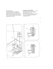
... you jerk your hand upwards lightly. The normal tension setting is in the white range between 3 and 5. Lower tension H = Regulating screw. K Lower tension too loose or upper tension too tight. J 4 I- 1 K 12 Upper tension (19) G = Setting mark. Turn it left for a looser tension, or right for a tighter tension. = Both tensions are correct. The correct lower tension Let the bobbin case with a full bobbin hang down by the thread. The higher the number, the tighter the...
... you jerk your hand upwards lightly. The normal tension setting is in the white range between 3 and 5. Lower tension H = Regulating screw. K Lower tension too loose or upper tension too tight. J 4 I- 1 K 12 Upper tension (19) G = Setting mark. Turn it left for a looser tension, or right for a tighter tension. = Both tensions are correct. The correct lower tension Let the bobbin case with a full bobbin hang down by the thread. The higher the number, the tighter the...
Owner's Manual
Page 17
As long as you button depressed, the machine keep sews this backwards. Dropping the machine feed Push drop-feed button 22 to G. '4 GH 13 CRnSnsaieneyhadeedisaesddtneellpogemeutfi,hnsoielhg1tous3otnti0sthsedh/eee7uoand0pwnnl5kesenaceswHrbfdeaaaflnwcarrei.rdenesTGag.dshlaIteeoinntnwsd(wewhairlpiortltdulhadlgltotnhhtt.heeheweTebfhlaaectnk) tighten screw G. Reverse sewing Push button 12. embroidery, darning etc.) For sewing, push the the bottom, and back drop-feed button again to position to The feed dog is dropped (for position H.
As long as you button depressed, the machine keep sews this backwards. Dropping the machine feed Push drop-feed button 22 to G. '4 GH 13 CRnSnsaieneyhadeedisaesddtneellpogemeutfi,hnsoielhg1tous3otnti0sthsedh/eee7uoand0pwnnl5kesenaceswHrbfdeaaaflnwcarrei.rdenesTGag.dshlaIteeoinntnwsd(wewhairlpiortltdulhadlgltotnhhtt.heeheweTebfhlaaectnk) tighten screw G. Reverse sewing Push button 12. embroidery, darning etc.) For sewing, push the the bottom, and back drop-feed button again to position to The feed dog is dropped (for position H.
Owner's Manual
Page 20
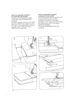
... screw N. Insert the pin of the foot, pull it taut and clamp it in hole K and attach the foot so that it bears against its stop. This determines the buttonhole length. 16 Push bracket M toward the back and hold it lever snap 6 to 807 set utility-stitch dial Push let it there. lever Insert the filler cord as follows (Fig. H = Darning foot Raise the needle bar. Buttonhole settings On models 5 to B. 802 to into buttonhole...
... screw N. Insert the pin of the foot, pull it taut and clamp it in hole K and attach the foot so that it bears against its stop. This determines the buttonhole length. 16 Push bracket M toward the back and hold it lever snap 6 to 807 set utility-stitch dial Push let it there. lever Insert the filler cord as follows (Fig. H = Darning foot Raise the needle bar. Buttonhole settings On models 5 to B. 802 to into buttonhole...
Owner's Manual
Page 22
... its two haoks enter the two holes in the machine base. Turn catch G on models 800, 802 and 806 The foot control receptacle of these models also serves as a detachable workplate. Turn the receptacle round and fit it against the bedplate. Swing the support down a little after fitting. (...workplate on models 601, 803 and 807 Push the workplate over the free arm until it snaps into place. To remove the workplate reverse this proced ure. 4HJ \ ilHIl .. ... 18 Press the workplate down (Fig. I) and press it to the machine so that its two guide pins enter the holes provided....
... its two haoks enter the two holes in the machine base. Turn catch G on models 800, 802 and 806 The foot control receptacle of these models also serves as a detachable workplate. Turn the receptacle round and fit it against the bedplate. Swing the support down a little after fitting. (...workplate on models 601, 803 and 807 Push the workplate over the free arm until it snaps into place. To remove the workplate reverse this proced ure. 4HJ \ ilHIl .. ... 18 Press the workplate down (Fig. I) and press it to the machine so that its two guide pins enter the holes provided....
Owner's Manual
Page 23
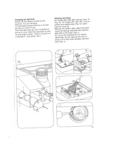
..., screws and needle plate remove cover 15 803, 807: remove (Fig. Remove the bobbin case. Pull out the plug. Push it out. H>. J). 19 Push the light bulb up and G that the top is in slots I. G). Clean round the sewing hook and the the parts machine fDdneraoeondpnceowo-tifftrohoeiliela.thisnAeolftlhtmyebaorcuhuhosihohnakev(eFraaisgtco.eitwId)i.oas ymisnaopiwuntteaand then (Fig. below, left.) Cleaning and oiling On models 800, 802, 806: (Fig. Open free arm cover 24. Changing the Switch off the light bulb...
..., screws and needle plate remove cover 15 803, 807: remove (Fig. Remove the bobbin case. Pull out the plug. Push it out. H>. J). 19 Push the light bulb up and G that the top is in slots I. G). Clean round the sewing hook and the the parts machine fDdneraoeondpnceowo-tifftrohoeiliela.thisnAeolftlhtmyebaorcuhuhosihohnakev(eFraaisgtco.eitwId)i.oas ymisnaopiwuntteaand then (Fig. below, left.) Cleaning and oiling On models 800, 802, 806: (Fig. Open free arm cover 24. Changing the Switch off the light bulb...
Owner's Manual
Page 24
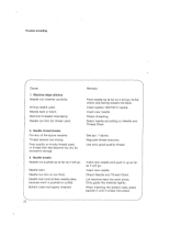
... Thread Chart. Wrong needle used . 2. Machine threaded improperly. Thread tension too strong. Insert new needle. Insert new needle and push it up as far as it will go . Only gujde th material lightly. Needle thread breaks For any of the above . Remedy: Push needle up as far as it snaps into place. Trouble shooting Cause: 1. Bobbin case improperly inserted. Use only good-quality thread. Needle too thin for thread used . Needle too thin or too thick. Let machine feed the work...
... Thread Chart. Wrong needle used . 2. Machine threaded improperly. Thread tension too strong. Insert new needle. Insert new needle and push it up as far as it will go . Only gujde th material lightly. Needle thread breaks For any of the above . Remedy: Push needle up as far as it snaps into place. Trouble shooting Cause: 1. Bobbin case improperly inserted. Use only good-quality thread. Needle too thin for thread used . Needle too thin or too thick. Let machine feed the work...
Owner's Manual
Page 25
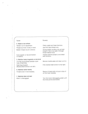
... upper and lower tensions. Machine does not start Motor is at all Lint has accumulated between tooth rows of oil into hook raceway. 7. Bobbin thread wound unevenly. During bobbin winding, do not hold thread in hook raceway. Flick reverse-feed control to the right. 6. Turn the motor disengaging switch until the knob points downwards. Thread too thick, knotty or hard. Feed dog dropped. (Reverse-feed control is disengaged. Remove thread ends and put a drop of feed dog. Seam is not uniform Tension...
... upper and lower tensions. Machine does not start Motor is at all Lint has accumulated between tooth rows of oil into hook raceway. 7. Bobbin thread wound unevenly. During bobbin winding, do not hold thread in hook raceway. Flick reverse-feed control to the right. 6. Turn the motor disengaging switch until the knob points downwards. Thread too thick, knotty or hard. Feed dog dropped. (Reverse-feed control is disengaged. Remove thread ends and put a drop of feed dog. Seam is not uniform Tension...


