WVSC385 User Guide
Page 1
Installation Guide Network Camera Model No. The model number is abbreviated in some descriptions in this manual for future use. WV-SC385 WV-SC385E WV-SC385 LOCK OPEN Before attempting to connect or operate this product, please read these instructions carefully and save this manual.
Installation Guide Network Camera Model No. The model number is abbreviated in some descriptions in this manual for future use. WV-SC385 WV-SC385E WV-SC385 LOCK OPEN Before attempting to connect or operate this product, please read these instructions carefully and save this manual.
WVSC385 User Guide
Page 7
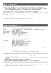
..., displaying of images may become slower or the web browser may become inoperable. • Audio may not be heard if a sound card is not installed on a PC. Adobe® Reader® is required to read the operating instructions on Windows Vista® / Windows® 7" (PDF) for...user manuals There are 2 sets of operating instructions for the WV-SC385 (NTSC model), WV-SC385E (PAL model) as follows. • Installation Guide: Explains how to install and connect devices, as well as how to connect and configure the network. • Operating Instructions (PDF): Explains how to perform the ...
..., displaying of images may become slower or the web browser may become inoperable. • Audio may not be heard if a sound card is not installed on a PC. Adobe® Reader® is required to read the operating instructions on Windows Vista® / Windows® 7" (PDF) for...user manuals There are 2 sets of operating instructions for the WV-SC385 (NTSC model), WV-SC385E (PAL model) as follows. • Installation Guide: Explains how to install and connect devices, as well as how to connect and configure the network. • Operating Instructions (PDF): Explains how to perform the ...
WVSC385 User Guide
Page 14
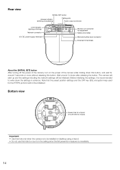
...protocol will be initialized. Before initializing the settings, it is recommended to mount on the ceiling since the fall prevention measure is to be installed on desktop using a tripod. • Do not use this button. Bottom view Screw hole for a tripod (1/4-20 UNC for tripod) ...more without releasing this hole to write down the settings in advance. Rear view INITIAL SET button Access indicator (blinking at accessing) Cable guide Audio output connector Link indicator (lighting at linking) Network connector 12 V DC power supply terminal 10BASE-T/ 100BASE-TX LINK ACT INITIAL ...
...protocol will be initialized. Before initializing the settings, it is recommended to mount on the ceiling since the fall prevention measure is to be installed on desktop using a tripod. • Do not use this button. Bottom view Screw hole for a tripod (1/4-20 UNC for tripod) ...more without releasing this hole to write down the settings in advance. Rear view INITIAL SET button Access indicator (blinking at accessing) Cable guide Audio output connector Link indicator (lighting at linking) Network connector 12 V DC power supply terminal 10BASE-T/ 100BASE-TX LINK ACT INITIAL ...
WVSC385 User Guide
Page 15
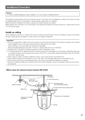
... the cover film from the 12 V DC power supply. wiring through a hole in the ceiling (☞ page 16) and wiring through a cable guide (unnecessary to make a hole in case the mount bracket comes off the power of the devices including the camera and the PC or disconnect from... F1.6 N·m {1.18 lbf·ft}, M6: F5.0 N·m {3.69 lbf·ft}) • Required pull-out capacity of the installation area. When installing on a desktop. Installations/Connections Caution: • FOR UL LISTED MODEL(S), ONLY CONNECT 12 V DC CLASS 2 POWER SUPPLY. In this case, wood screws and nails should ...
... the cover film from the 12 V DC power supply. wiring through a hole in the ceiling (☞ page 16) and wiring through a cable guide (unnecessary to make a hole in case the mount bracket comes off the power of the devices including the camera and the PC or disconnect from... F1.6 N·m {1.18 lbf·ft}, M6: F5.0 N·m {3.69 lbf·ft}) • Required pull-out capacity of the installation area. When installing on a desktop. Installations/Connections Caution: • FOR UL LISTED MODEL(S), ONLY CONNECT 12 V DC CLASS 2 POWER SUPPLY. In this case, wood screws and nails should ...
WVSC385 User Guide
Page 17
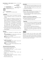
... IN2, 3) by configuring the setting. When it is provided only for checking the adjustment of the angular field of view on the video monitor when installing the camera or when servicing. It is "ALARM IN 3". The default of EXT I/O terminal 2 is "ALARM IN 2" and of the camera mount bracket. ...) (Audio output is not changed.) Step 6 Mount the camera onto the camera mount bracket (accessory). Fit the lock plate of the camera onto the guide part of the camera mount bracket, and rotate the camera clockwise after turning off the power of the camera (screw hole for "Terminal alarm 2" or...
... IN2, 3) by configuring the setting. When it is provided only for checking the adjustment of the angular field of view on the video monitor when installing the camera or when servicing. It is "ALARM IN 3". The default of EXT I/O terminal 2 is "ALARM IN 2" and of the camera mount bracket. ...) (Audio output is not changed.) Step 6 Mount the camera onto the camera mount bracket (accessory). Fit the lock plate of the camera onto the guide part of the camera mount bracket, and rotate the camera clockwise after turning off the power of the camera (screw hole for "Terminal alarm 2" or...
WVSC385 User Guide
Page 23
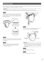
...that is fixed on the camera mount bracket using the fixing screw. It may result in a different way from the camera. Decorative cover guide WV-SC385 LOCK OPEN LOCK OPEN LOCK OPEN Step 4 Rotate the camera counterclockwise to detach the camera from the camera. 23 Step 6 Detach...) counterclockwise until the indication "OPEN" reached the decorative cover guide of the camera. Main body of the camera Moving part Important: • When detaching the camera from the camera, and then turn off the power of installation on the camera mount bracket (accessory). Do not lose the...
...that is fixed on the camera mount bracket using the fixing screw. It may result in a different way from the camera. Decorative cover guide WV-SC385 LOCK OPEN LOCK OPEN LOCK OPEN Step 4 Rotate the camera counterclockwise to detach the camera from the camera. 23 Step 6 Detach...) counterclockwise until the indication "OPEN" reached the decorative cover guide of the camera. Main body of the camera Moving part Important: • When detaching the camera from the camera, and then turn off the power of installation on the camera mount bracket (accessory). Do not lose the...
WVSC385 User Guide
Page 34
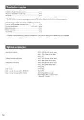
...1 pc. * The CD-ROM contains the operating instructions (PDFs) and different kinds of tool software programs. The following parts are used during installation procedures. Optional accessories Wall Mount Bracket Ceiling Embedding Bracket Ceiling Mount Bracket Inner Cover User License Accessory (For MPEG-4) User License Accessory (For H.... Power cord plug 1 pc. Camera fixing screw 2 pcs. (incl. 1 spare) Decorative cover 1 pc. Camera mount bracket (w/safety wire 1 pc. Standard accessories Installation Guide (this document 1 pc. The network administrator shall retain the code label.
...1 pc. * The CD-ROM contains the operating instructions (PDFs) and different kinds of tool software programs. The following parts are used during installation procedures. Optional accessories Wall Mount Bracket Ceiling Embedding Bracket Ceiling Mount Bracket Inner Cover User License Accessory (For MPEG-4) User License Accessory (For H.... Power cord plug 1 pc. Camera fixing screw 2 pcs. (incl. 1 spare) Decorative cover 1 pc. Camera mount bracket (w/safety wire 1 pc. Standard accessories Installation Guide (this document 1 pc. The network administrator shall retain the code label.


