Network Camera
Page 1
Network Camera Operating Instructions Model No. WV-NW484S Before attempting to connect or operate this product, please read these instructions carefully and save this manual for future use.
Network Camera Operating Instructions Model No. WV-NW484S Before attempting to connect or operate this product, please read these instructions carefully and save this manual for future use.

Network Camera
Page 2
... interference to radio communications. Any changes or modifications not expressly approved by qualified service personnel or system installers. • The connections should comply with local electrical code. You should note the serial number of this unit in accordance with Canadian ICES-003. Model No. NO USER-SERVICEABLE PARTS INSIDE. For Canada This Class A digital apparatus complies with the instruction manual, may be made by...
... interference to radio communications. Any changes or modifications not expressly approved by qualified service personnel or system installers. • The connections should comply with local electrical code. You should note the serial number of this unit in accordance with Canadian ICES-003. Model No. NO USER-SERVICEABLE PARTS INSIDE. For Canada This Class A digital apparatus complies with the instruction manual, may be made by...
Network Camera
Page 5
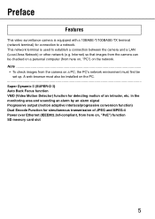
Preface Features This video surveillance camera is used to a network. Internet) so that images from the camera can be set up. A web browser must first be checked on a personal computer (from here on, "PoE") function SD memory card slot 5 in the monitoring area and sounding an alarm by an alarm signal Progressive output (motion adaptive interlace/progressive conversion function) Dual Encode Function for simultaneous transmission of an intruder, etc. Not.e...•...
Preface Features This video surveillance camera is used to a network. Internet) so that images from the camera can be set up. A web browser must first be checked on a personal computer (from here on, "PoE") function SD memory card slot 5 in the monitoring area and sounding an alarm by an alarm signal Progressive output (motion adaptive interlace/progressive conversion function) Dual Encode Function for simultaneous transmission of an intruder, etc. Not.e...•...
Network Camera
Page 6
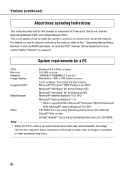
... camera, refer to connect and set up the network. Preface (continued) About these operating instructions The Instruction Manual for reading Operating Instructions in CD-ROM) Not.e... • When the PC is used in an environment other problems may occur... 6 This book explains how to install the camera, and how to the " Operating Manual/Setup Manual" in the web browser may no longer be possible, or other than that recommended, the image...
... camera, refer to connect and set up the network. Preface (continued) About these operating instructions The Instruction Manual for reading Operating Instructions in CD-ROM) Not.e... • When the PC is used in an environment other problems may occur... 6 This book explains how to install the camera, and how to the " Operating Manual/Setup Manual" in the web browser may no longer be possible, or other than that recommended, the image...
Network Camera
Page 7
Network Security As you will use this product connected to a network, your attention is called to protect your network against leakage or theft of information, including image data, authentication information (user names and passwords), alarm mail information, FTP server information and DDNS server information. • Do not install the camera in these operating instructions may be destroyed or damaged by persons with malicious intent It is your network against unauthorized...
Network Security As you will use this product connected to a network, your attention is called to protect your network against leakage or theft of information, including image data, authentication information (user names and passwords), alarm mail information, FTP server information and DDNS server information. • Do not install the camera in these operating instructions may be destroyed or damaged by persons with malicious intent It is your network against unauthorized...
Network Camera
Page 8
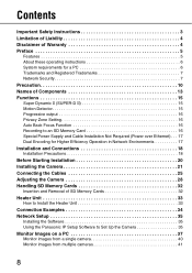
... Operation in Network Environments 17 Installation and Connections 18 Installation Precautions 18 Before Starting Installation 20 Installing the Camera 21 Connecting the Cables 25 Adjusting the Camera 28 Handling SD Memory Cards 32 Insertion and Removal of SD Memory Cards 32 Heater Unit 33 How to Install the Heater Unit 33 Connection Examples 34 Network Setup 35 Installing the Software 35 Using the Panasonic IP Setup Software to Set Up the Camera 35 Monitor Images on a PC 37 Monitor images from a single camera...
... Operation in Network Environments 17 Installation and Connections 18 Installation Precautions 18 Before Starting Installation 20 Installing the Camera 21 Connecting the Cables 25 Adjusting the Camera 28 Handling SD Memory Cards 32 Insertion and Removal of SD Memory Cards 32 Heater Unit 33 How to Install the Heater Unit 33 Connection Examples 34 Network Setup 35 Installing the Software 35 Using the Panasonic IP Setup Software to Set Up the Camera 35 Monitor Images on a PC 37 Monitor images from a single camera...
Network Camera
Page 10
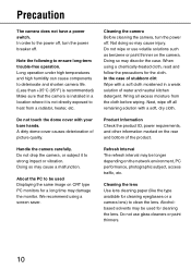
... be used Displaying the same image on the network environment, PC performance, photographic subject, access traffic, etc. Next, wipe off all excess moisture from a radiator, heater, etc. Do not drop the camera, or subject it is installed in a weak solution of stubborn dirt Wipe with a soft cloth moistened in a location where it to ensure long-term trouble-free operation. About...
... be used Displaying the same image on the network environment, PC performance, photographic subject, access traffic, etc. Next, wipe off all excess moisture from a radiator, heater, etc. Do not drop the camera, or subject it is installed in a weak solution of stubborn dirt Wipe with a soft cloth moistened in a location where it to ensure long-term trouble-free operation. About...
Network Camera
Page 14
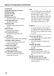
... Mounting bracket (accessory) (3) Network cable (4) Alarm I/O cable (5) Power cable (6) Tilting lock screw Fixes the tilt position after adjusting. (7) Tilt adjustment seat Adjusts the screen tilt. (8) Panning table Adjusts the horizontal angle of the ABF. (19) Monitor output jack Used for connecting the monitor for turning the link LED and access LED on and off . Not.e The link LED and the access LED light if the LED ON/OFF button is ON and the LED display setting (→ Setup Manual) on screen. (16) Access LED (ACT) This LED indicates the reception status. (17) Link LED (LINK) This LED...
... Mounting bracket (accessory) (3) Network cable (4) Alarm I/O cable (5) Power cable (6) Tilting lock screw Fixes the tilt position after adjusting. (7) Tilt adjustment seat Adjusts the screen tilt. (8) Panning table Adjusts the horizontal angle of the ABF. (19) Monitor output jack Used for connecting the monitor for turning the link LED and access LED on and off . Not.e The link LED and the access LED light if the LED ON/OFF button is ON and the LED display setting (→ Setup Manual) on screen. (16) Access LED (ACT) This LED indicates the reception status. (17) Link LED (LINK) This LED...
Network Camera
Page 16
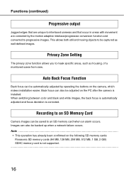
... images. When switching between color and black and white images, the back focus is automatically adjusted and focus deviation is not supported...16 Recording to an SD Memory Card Camera images can also be automatically adjusted by the motion adaptive interlace/progressive conversion function and converted to an SD memory card when an alarm occurs. Privacy Zone Setting The privacy zone function allows you to be backed up when a network...
... images. When switching between color and black and white images, the back focus is automatically adjusted and focus deviation is not supported...16 Recording to an SD Memory Card Camera images can also be automatically adjusted by the motion adaptive interlace/progressive conversion function and converted to an SD memory card when an alarm occurs. Privacy Zone Setting The privacy zone function allows you to be backed up when a network...
Network Camera
Page 17
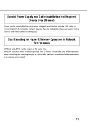
... the camera and video cables is not required. MPEG-4 operation when monitoring in real time or from a remote site, and JPEG operation when recording and verifying images at high quality can both be output at the same time in Network Environments MPEG-4 and JPEG can be supplied to the camera and images transmitted on a single LAN cable by connecting to PoE-compatible network devices. Special Power Supply and Cable Installation Not Required (Power over Ethernet) Power can...
... the camera and video cables is not required. MPEG-4 operation when monitoring in real time or from a remote site, and JPEG operation when recording and verifying images at high quality can both be output at the same time in Network Environments MPEG-4 and JPEG can be supplied to the camera and images transmitted on a single LAN cable by connecting to PoE-compatible network devices. Special Power Supply and Cable Installation Not Required (Power over Ethernet) Power can...

Network Camera
Page 19
... a network. • Wire and install the camera so that each screw is no unevenness and that the network will not be tightened sufficiently in accordance with this case, setup a specialized thin conduit and pass the cable through it can be ordered separately. Screws should be influenced by PoE Use a PoE-compatible (IEEE802.3afcompliant) hub or power supply unit. Choose screws in accordance with screws. Network Connection...
... a network. • Wire and install the camera so that each screw is no unevenness and that the network will not be tightened sufficiently in accordance with this case, setup a specialized thin conduit and pass the cable through it can be ordered separately. Screws should be influenced by PoE Use a PoE-compatible (IEEE802.3afcompliant) hub or power supply unit. Choose screws in accordance with screws. Network Connection...
Network Camera
Page 29
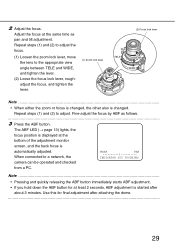
... time as follows...3 Press the ABF button. Repeat steps (1) and (2) to a network, the camera can be operated and checked from a PC. Not.e...• Pressing and quickly releasing the ABF button immediately starts ABF adjustment. • If you hold down the ABF button for final adjustment after about 3 minutes. Use this for at the bottom of the adjustment monitor screen, and the back focus is automatically adjusted...
... time as follows...3 Press the ABF button. Repeat steps (1) and (2) to a network, the camera can be operated and checked from a PC. Not.e...• Pressing and quickly releasing the ABF button immediately starts ABF adjustment. • If you hold down the ABF button for final adjustment after about 3 minutes. Use this for at the bottom of the adjustment monitor screen, and the back focus is automatically adjusted...

Network Camera
Page 30
... when adjusting method is set to "AUTO" or "PRESET". (→ Setup Manual) • How to Use the Varifocal Lens and Zoom Lens Before adjustment, reset the back focus position, and return the CS mount to Focus (when capturing subjects in as dark conditions as possible. • How to its default position. (→ Setup Manual) ...30 Focus can be out-of-focus when the iris is opened. The back focus setup dialog box is displayed. Adjusting the Camera...
... when adjusting method is set to "AUTO" or "PRESET". (→ Setup Manual) • How to Use the Varifocal Lens and Zoom Lens Before adjustment, reset the back focus position, and return the CS mount to Focus (when capturing subjects in as dark conditions as possible. • How to its default position. (→ Setup Manual) ...30 Focus can be out-of-focus when the iris is opened. The back focus setup dialog box is displayed. Adjusting the Camera...
Network Camera
Page 34
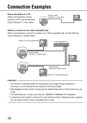
... recording or monitoring images. • Text displayed on the monitor screen may be clipped depending on the monitor you are not required when a PoE-compatible hub is used must be 10BASE-T/100BASE-TX-compatible. • A separate power supply is intended solely for each network camera. Monitor (for setup adjustments) PoE-compatible hub Ethernet cable (category 5, straight cable) Ethernet cable (category 5, straight cable) Monitor (for setup adjustments) Important • The monitor is required for checking the view angle during installation or servicing. Connection...
... recording or monitoring images. • Text displayed on the monitor screen may be clipped depending on the monitor you are not required when a PoE-compatible hub is used must be 10BASE-T/100BASE-TX-compatible. • A separate power supply is intended solely for each network camera. Monitor (for setup adjustments) PoE-compatible hub Ethernet cable (category 5, straight cable) Ethernet cable (category 5, straight cable) Monitor (for setup adjustments) Important • The monitor is required for checking the view angle during installation or servicing. Connection...
Network Camera
Page 35
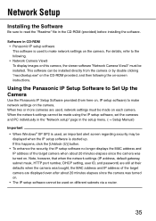
...) before installing the software. Software in the setup menu. (→ Setup Manual) Important • When Windows® XP SP2 is started up. Note, however, that when the network settings (IP address, default gateway, subnet mask, HTTP port number, DHCP setting, user ID, and password) are still at their defaults when the camera was bought, the MAC address and IP address of the target camera when about 20 minutes elapses since the camera was turned on...
...) before installing the software. Software in the setup menu. (→ Setup Manual) Important • When Windows® XP SP2 is started up. Note, however, that when the network settings (IP address, default gateway, subnet mask, HTTP port number, DHCP setting, user ID, and password) are still at their defaults when the camera was bought, the MAC address and IP address of the target camera when about 20 minutes elapses since the camera was turned on...
Network Camera
Page 36
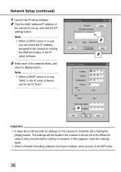
... this happens, make the settings again. • When a firewall (including software) has been installed, allow access of all UDP ports. 36 The settings will be set to "Auto". 3 Important • It takes about 30 seconds for settings on the camera to set up, and click the [IP setting] button. Network Setup (continued) 1 Launch the IP setup software. 2 Click the MAC address/IP address of the camera to complete after clicking the...
... this happens, make the settings again. • When a firewall (including software) has been installed, allow access of all UDP ports. 36 The settings will be set to "Auto". 3 Important • It takes about 30 seconds for settings on the camera to set up, and click the [IP setting] button. Network Setup (continued) 1 Launch the IP setup software. 2 Click the MAC address/IP address of the camera to complete after clicking the...

Network Camera
Page 41
... be used in a local area network, configure the web browser to bypass the proxy server for up to 8 cameras (2 groups) can be displayed depending on a multi-screen. • When the power is turned off or the LAN cable is "12345". Monitor images from multiple cameras Images from the "Live" page will become unavailable. 41 To enhance the security, be sure to change the password for the user name "admin". (→ Setup Manual) • When displaying...
... be used in a local area network, configure the web browser to bypass the proxy server for up to 8 cameras (2 groups) can be displayed depending on a multi-screen. • When the power is turned off or the LAN cable is "12345". Monitor images from multiple cameras Images from the "Live" page will become unavailable. 41 To enhance the security, be sure to change the password for the user name "admin". (→ Setup Manual) • When displaying...
Network Camera
Page 46
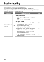
PoE power supply • Is the network cable connected to the power - Troubleshooting Before requesting service, check the following items. Also, check the description in the Operating Instructions, Setup Manual. Symptoms Check item/remedy page Camera does not turn on. ▲ AC/DC power supply • Is the power firmly connected to a PoE- 34 compatible power supply unit by an Ethernet (Category 5) cable? Make sure that can connect - Contact your dealer if a problem cannot be solved even after...
PoE power supply • Is the network cable connected to the power - Troubleshooting Before requesting service, check the following items. Also, check the description in the Operating Instructions, Setup Manual. Symptoms Check item/remedy page Camera does not turn on. ▲ AC/DC power supply • Is the power firmly connected to a PoE- 34 compatible power supply unit by an Ethernet (Category 5) cable? Make sure that can connect - Contact your dealer if a problem cannot be solved even after...

Network Camera
Page 48
Specifications (continued) Shutter speed Electronic sensitivity enhancement White balance Digital noise reduction Electronic zoom Camera title VMD alarm Scene change detection alarm Privacy zone • Lens Type Focal length F number Focus range Angle of view Adjusting angle • Network Network Image resolution Image MPEG-4 compression system JPEG Refresh interval Total bit rate Supported protocol OFF (1/60), AUTO, 1/100 Max. 32X ATW1/ATW2/AWC LOW/HIGH Max. 3X Max. 16 character display (alphanumeric characters, marks) ON...
Specifications (continued) Shutter speed Electronic sensitivity enhancement White balance Digital noise reduction Electronic zoom Camera title VMD alarm Scene change detection alarm Privacy zone • Lens Type Focal length F number Focus range Angle of view Adjusting angle • Network Network Image resolution Image MPEG-4 compression system JPEG Refresh interval Total bit rate Supported protocol OFF (1/60), AUTO, 1/100 Max. 32X ATW1/ATW2/AWC LOW/HIGH Max. 3X Max. 16 character display (alphanumeric characters, marks) ON...
Network Camera
Page 49
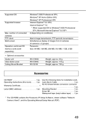
... g Weight, approx. 110 g Weight, approx. 705 g Accessories CD-ROM 1 pc. Operating Instructions (this book) . . . . .1 pc. RJ-45 female-female conversion connector 1 pc. Waterproof tape (butyl rubber tape) . . . 1 pc. * The CD-ROM contains the Panasonic IP Setup Software, viewer software "Network Camera View3", and the Operating Manual/Setup Manual (PDF). 49 Use the following items for installation work. 4-pin Alarm Cable 1 pc. Warranty Certificate 1 Label (MAC address 1 pc. Driver Bit 1 pc. Mounting Bracket 1 pc. Supported OS Supported browser Max.
... g Weight, approx. 110 g Weight, approx. 705 g Accessories CD-ROM 1 pc. Operating Instructions (this book) . . . . .1 pc. RJ-45 female-female conversion connector 1 pc. Waterproof tape (butyl rubber tape) . . . 1 pc. * The CD-ROM contains the Panasonic IP Setup Software, viewer software "Network Camera View3", and the Operating Manual/Setup Manual (PDF). 49 Use the following items for installation work. 4-pin Alarm Cable 1 pc. Warranty Certificate 1 Label (MAC address 1 pc. Driver Bit 1 pc. Mounting Bracket 1 pc. Supported OS Supported browser Max.


