
Operating Instructions
Page 1
Before attempting to connect or operate this product, please read these instructions carefully and save this manual for future use. ENGLISH Color CCTV Camera Operating Instructions WV-CS954 Model No. FRANÇAIS
Before attempting to connect or operate this product, please read these instructions carefully and save this manual for future use. ENGLISH Color CCTV Camera Operating Instructions WV-CS954 Model No. FRANÇAIS

Operating Instructions
Page 4
... CLAIM OR ACTION FOR DAMAGES, BROUGHT BY ANY PERSON OR ORGANIZATION BEING PHOTOGENIC SUBJECT, DUE TO VIOLATION OF PRIVACY WITH THE RESULT OF THAT SURVEILLANCE-CAMERA's PICTURE, INCLUDING SAVED DATA, FOR SOME REASON, BECOMES PUBLIC OR IS USED FOR THE PURPOSE OTHER THAN SURVEILLANCE. (7) ANY PROBLEM, CONSEQUENTIAL INCONVENIENCE, ANY LOSS OR...
... CLAIM OR ACTION FOR DAMAGES, BROUGHT BY ANY PERSON OR ORGANIZATION BEING PHOTOGENIC SUBJECT, DUE TO VIOLATION OF PRIVACY WITH THE RESULT OF THAT SURVEILLANCE-CAMERA's PICTURE, INCLUDING SAVED DATA, FOR SOME REASON, BECOMES PUBLIC OR IS USED FOR THE PURPOSE OTHER THAN SURVEILLANCE. (7) ANY PROBLEM, CONSEQUENTIAL INCONVENIENCE, ANY LOSS OR...

Operating Instructions
Page 5
... 1 pc. Warranty Certificate 1 pc. OPTIONAL ACCESORIES Dome Cover(approx.50 % transparency,smoked type WV-CS3S Ceiling Mount Bracket WV-Q105/WV-Q116/WV-Q117 Wall Mount Bracket WV-Q118 -5- This function can be used to structure a system with up to 256 camera positions. Decorative Cover 1 pc. This makes it possible to 180° in a single motion...
... 1 pc. Warranty Certificate 1 pc. OPTIONAL ACCESORIES Dome Cover(approx.50 % transparency,smoked type WV-CS3S Ceiling Mount Bracket WV-Q105/WV-Q116/WV-Q117 Wall Mount Bracket WV-Q118 -5- This function can be used to structure a system with up to 256 camera positions. Decorative Cover 1 pc. This makes it possible to 180° in a single motion...
Operating Instructions
Page 6
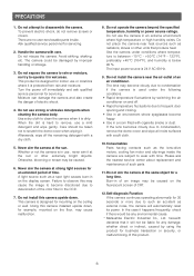
...reset its power. Please ask the nearest service center about replacement and maintenance of an air conditioner. Self-diagnosis Function If the camera continues operating abnormally for mounting on the ceiling or wall. Use a dry cloth to scratch the dome cover when wiping it...electric shock. 4. herewith declares that produce heat. When the dirt is below 90 %. Avoid striking, shaking, etc. Do not operate the camera beyond the specified temperature, humidity or power source ratings. Turn the power off . • Rapid temperature fluctuations due to frequent door opening and...
...reset its power. Please ask the nearest service center about replacement and maintenance of an air conditioner. Self-diagnosis Function If the camera continues operating abnormally for mounting on the ceiling or wall. Use a dry cloth to scratch the dome cover when wiping it...electric shock. 4. herewith declares that produce heat. When the dirt is below 90 %. Avoid striking, shaking, etc. Do not operate the camera beyond the specified temperature, humidity or power source ratings. Turn the power off . • Rapid temperature fluctuations due to frequent door opening and...
Operating Instructions
Page 7
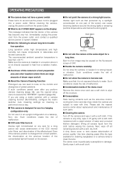
... susceptible to wear with a weak solution of water and a neutral kitchen detergent. Bright Subject Smearing Blooming ■ Do not aim the camera at the previous location of the concentrated light will remain on one part of the screen can cause blooming (rainbow around the strong light)..., and discoloration of the affected part. free operation Long operation under high temperatures and high humidity can cause components to water. If you perform camera cleaning (page 35), use a soft cloth to wipe off gently with a soft cloth moistened with time. Do not use in an upright...
... susceptible to wear with a weak solution of water and a neutral kitchen detergent. Bright Subject Smearing Blooming ■ Do not aim the camera at the previous location of the concentrated light will remain on one part of the screen can cause blooming (rainbow around the strong light)..., and discoloration of the affected part. free operation Long operation under high temperatures and high humidity can cause components to water. If you perform camera cleaning (page 35), use a soft cloth to wipe off gently with a soft cloth moistened with time. Do not use in an upright...

Operating Instructions
Page 8
...reset itself and restore normal operation. Uploading of WV-CS954 preset data to other reason continues for more than 30 seconds, the camera will not end normally if it could mean that can cause malfunction of the camera, so you should contact a qualified service person... and menu settings. ■ Downloading (saving) or uploading (recovering) camera setting information Camera setting information that the camera is installed in a location where there is a large amount of external noise. WV-CS854, WV-CS854A, WV-CS854B and WVNS324) may cause an error and failure of the uploading ...
...reset itself and restore normal operation. Uploading of WV-CS954 preset data to other reason continues for more than 30 seconds, the camera will not end normally if it could mean that can cause malfunction of the camera, so you should contact a qualified service person... and menu settings. ■ Downloading (saving) or uploading (recovering) camera setting information Camera setting information that the camera is installed in a location where there is a large amount of external noise. WV-CS854, WV-CS854A, WV-CS854B and WVNS324) may cause an error and failure of the uploading ...

Operating Instructions
Page 9
... ■ Auto Nighttime Switching to Black and White Mode 5 ■ Digital Flip 5 ■ Privacy Zone Function 5 ■ Patrol Function 5 ■ Camera Position Memory 5 ■ Motion Detection 5 ACCESORIES 5 OPTIONAL ACCESORIES 5 PRECAUTIONS 6 OPERATING PRECAUTIONS 7 CONSTRUCTION 10 INSTALLATION PRECAUTIONS 11 DIP SWITCH SETTINGS 12 ■... SETUP 20 USING THE SETUP MENU 21 ■ Displaying the Setup Menu 21 ■ Language Setting 21 CAMERA SETTINGS 22 ■ Using the Camera Setup Menu 22 PAN / TILT 27 ■ Using the Pan/Tilt Setup Menu 27 ALARM SETTINGS 36 ...
... ■ Auto Nighttime Switching to Black and White Mode 5 ■ Digital Flip 5 ■ Privacy Zone Function 5 ■ Patrol Function 5 ■ Camera Position Memory 5 ■ Motion Detection 5 ACCESORIES 5 OPTIONAL ACCESORIES 5 PRECAUTIONS 6 OPERATING PRECAUTIONS 7 CONSTRUCTION 10 INSTALLATION PRECAUTIONS 11 DIP SWITCH SETTINGS 12 ■... SETUP 20 USING THE SETUP MENU 21 ■ Displaying the Setup Menu 21 ■ Language Setting 21 CAMERA SETTINGS 22 ■ Using the Camera Setup Menu 22 PAN / TILT 27 ■ Using the Pan/Tilt Setup Menu 27 ALARM SETTINGS 36 ...
Operating Instructions
Page 10
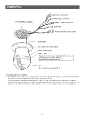
... quality and noise, it replaced. -10- Lens The lens cannot be handled with care. Ensuring Trouble-free Operation • This camera uses a "slip ring" for Camera Safety Wire Decorative Cover (provided) Dome Anchor Ring Dome Cover Rotate the dome anchor ring to the left to remove it. In... mean that the slip ring has reached the end of its service life. Contact a qualified service person or system installer to ensure trouble-free camera operation, make sure that the cleaning function (page 35) is easily damaged, and should be replaced. A dirty slip ring can cause deterioration...
... quality and noise, it replaced. -10- Lens The lens cannot be handled with care. Ensuring Trouble-free Operation • This camera uses a "slip ring" for Camera Safety Wire Decorative Cover (provided) Dome Anchor Ring Dome Cover Rotate the dome anchor ring to the left to remove it. In... mean that the slip ring has reached the end of its service life. Contact a qualified service person or system installer to ensure trouble-free camera operation, make sure that the cleaning function (page 35) is easily damaged, and should be replaced. A dirty slip ring can cause deterioration...
Operating Instructions
Page 11
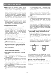
...boat, or other area subjected to temperature extremes (Such conditions can cause malfunction and shorten the life of the camera. ■ Install the camera in the camera, Panasonic holds absolutely no responsibility for accidents caused by fault in a horizontal configuration, with screws. It is not ... strength (like a drop ceiling), use the optionally available WV-Q105 Direct Attachment Ceiling Mounting Bracket or the WV-Q116 Embedded Ceiling Mount Bracket. • For ceiling mounting, use the optionally available WV-Q117 Ceiling Mount Bracket. • For wall mounting, use...
...boat, or other area subjected to temperature extremes (Such conditions can cause malfunction and shorten the life of the camera. ■ Install the camera in the camera, Panasonic holds absolutely no responsibility for accidents caused by fault in a horizontal configuration, with screws. It is not ... strength (like a drop ceiling), use the optionally available WV-Q105 Direct Attachment Ceiling Mounting Bracket or the WV-Q116 Embedded Ceiling Mount Bracket. • For ceiling mounting, use the optionally available WV-Q117 Ceiling Mount Bracket. • For wall mounting, use...
Operating Instructions
Page 12
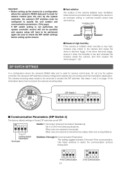
...unit number and communication parameters. (This page) If DIP switch setting is not performed, the system controller control will not be possible and camera setup will have to check the DIP switch settings before setting up . Ventilation holes ■ Beware of these switches to remove the... camera mounting base. DIP Switch 1 ON DIP Switch 2 ON 12345678 1234 ■ Communication Parameters (DIP Switch 2) The factory default settings of high humidity. Use...
...unit number and communication parameters. (This page) If DIP switch setting is not performed, the system controller control will not be possible and camera setup will have to check the DIP switch settings before setting up . Ventilation holes ■ Beware of these switches to remove the... camera mounting base. DIP Switch 1 ON DIP Switch 2 ON 12345678 1234 ■ Communication Parameters (DIP Switch 2) The factory default settings of high humidity. Use...
Operating Instructions
Page 14
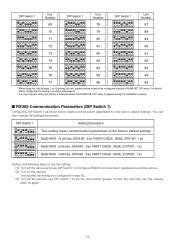
For details about configuring this setting, see step 2 and page 20. * Turning on power when this setting. (1) Turn off the camera, use DIP Switch 1 to appear during the initialization routine. ■ RS485 Communication Parameters (DIP Switch 1) Configuring DIP Switch 1 as desired. ...configure RS485 communication parameters as shown above. (2) Turn on again. -14- This applies the setting you configured in step (1). (3) Turn off the camera and use DIP Switch 1 to their factory default settings. DIP Switch 1 Unit Number DIP Switch 1 Unit Number DIP Switch 1 Unit Number ON ...
For details about configuring this setting, see step 2 and page 20. * Turning on power when this setting. (1) Turn off the camera, use DIP Switch 1 to appear during the initialization routine. ■ RS485 Communication Parameters (DIP Switch 1) Configuring DIP Switch 1 as desired. ...configure RS485 communication parameters as shown above. (2) Turn on again. -14- This applies the setting you configured in step (1). (3) Turn off the camera and use DIP Switch 1 to their factory default settings. DIP Switch 1 Unit Number DIP Switch 1 Unit Number DIP Switch 1 Unit Number ON ...

Operating Instructions
Page 15
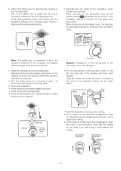
...drill the hole. See steps 1 and 2 below when mounting the camera on the camera and then remove it . Rotate 15° Pull the camera mounting base up to remove it will not become lost. Installing the camera at the locations you are working. Remove the fixing screw (M3 ... locations of pliers. 2. Use screws (M4) at a location that secures the camera to the mounting base. If you are using the top cable exit configuration, mark the location of the camera. Affix the camera mounting base onto the ceiling. Screws (M4, available separately) Dust Protection Sheet (comes...
...drill the hole. See steps 1 and 2 below when mounting the camera on the camera and then remove it . Rotate 15° Pull the camera mounting base up to remove it will not become lost. Installing the camera at the locations you are working. Remove the fixing screw (M3 ... locations of pliers. 2. Use screws (M4) at a location that secures the camera to the mounting base. If you are using the top cable exit configuration, mark the location of the camera. Affix the camera mounting base onto the ceiling. Screws (M4, available separately) Dust Protection Sheet (comes...
Operating Instructions
Page 16
... exit configuration, slide the decorative cover straight up to the mounting base. 8. Top Cable Exit Configuration Side Cable Exit Configuration Align with camera). Install the camera onto the mounting base. Slide the decorative cover up and press it . 10. Use the fixing screw you try to hang from ...each other piece. Back Align hook Hold securely Press Hold securely Press 15° Camera Rotate Camera Mounting Base 11. Separate the two parts of the decorative cover can damage it firmly against the ceiling. Put the two pieces of...
... exit configuration, slide the decorative cover straight up to the mounting base. 8. Top Cable Exit Configuration Side Cable Exit Configuration Align with camera). Install the camera onto the mounting base. Slide the decorative cover up and press it . 10. Use the fixing screw you try to hang from ...each other piece. Back Align hook Hold securely Press Hold securely Press 15° Camera Rotate Camera Mounting Base 11. Separate the two parts of the decorative cover can damage it firmly against the ceiling. Put the two pieces of...

Operating Instructions
Page 17
... by the arrow and remove it . 1. Failure to do so creates the risk of damage to the camera. ■ Removing the Decorative Camera Note that secures the camera to remove it . Fixing screw After loosening the screw, press upwards on the side of the decorative cover... (indicated by the arrows, in the illustration below carefully and exactly when uninstalling the camera and decorative cover. Rotate the camera in a place where it . 15° Rotate Camera Camera Mounting Base 3. Remove the camera from the mounting base. -17- Unhook the two parts of the decorative cover....
... by the arrow and remove it . 1. Failure to do so creates the risk of damage to the camera. ■ Removing the Decorative Camera Note that secures the camera to remove it . Fixing screw After loosening the screw, press upwards on the side of the decorative cover... (indicated by the arrows, in the illustration below carefully and exactly when uninstalling the camera and decorative cover. Rotate the camera in a place where it . 15° Rotate Camera Camera Mounting Base 3. Remove the camera from the mounting base. -17- Unhook the two parts of the decorative cover....
Operating Instructions
Page 18
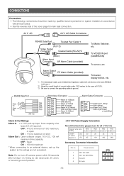
... mA maximum drive capacity OFF : Open ON : 100 mA maximum * When connecting to an external device, set up input. Note: Do not turn off camera power within 30 seconds after turning it on. RS485 Data Port Data Tx Data Rx Red Orange Yellow Green (RJ-12) T(B) T(A) R(B) R(A) Alarm Input Connector... so can cause pan, tilt, zoom, or focus to go out of position. • 24 V AC Power Supply Connection Recommended wire gauge sizes for camera RS485 Data Port Twisted Pair Cable*1 (RJ-12) Video Output Connector Coaxial Cable (5C-2V)*2 (BNC) Alarm Input Connector 8P Alarm Cable (provided) To...
... mA maximum drive capacity OFF : Open ON : 100 mA maximum * When connecting to an external device, set up input. Note: Do not turn off camera power within 30 seconds after turning it on. RS485 Data Port Data Tx Data Rx Red Orange Yellow Green (RJ-12) T(B) T(A) R(B) R(A) Alarm Input Connector... so can cause pan, tilt, zoom, or focus to go out of position. • 24 V AC Power Supply Connection Recommended wire gauge sizes for camera RS485 Data Port Twisted Pair Cable*1 (RJ-12) Video Output Connector Coaxial Cable (5C-2V)*2 (BNC) Alarm Input Connector 8P Alarm Cable (provided) To...
Operating Instructions
Page 19
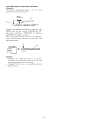
.... . 33 mmmm{{00.1.1"}"} UUpp A Insert WWiriere IInnsseertrtththeewwireireunutniltAil Apopsoitisointion aannddcclalammppthtehecocnotanctatsc. Do not shrink the cable-entry seal until they snap in the accessory connector of this camera until ascertaining that the unit is a one-time procedure. ts. Prepare the individual conductors for clamping the contacts.
.... . 33 mmmm{{00.1.1"}"} UUpp A Insert WWiriere IInnsseertrtththeewwireireunutniltAil Apopsoitisointion aannddcclalammppthtehecocnotanctatsc. Do not shrink the cable-entry seal until they snap in the accessory connector of this camera until ascertaining that the unit is a one-time procedure. ts. Prepare the individual conductors for clamping the contacts.
Operating Instructions
Page 20
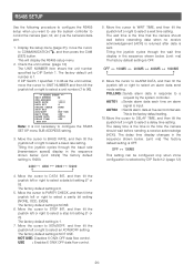
... time display changes in the sequence shown below. (unit: bits/s) The factory default setting is not necessary to control the camera (pan, tilt, etc.) via the camera's data port. 1. The factory default unit number is the factory default setting. 10. Tilting the joystick cycles through the wait... 2. The factory default setting is 1. 7. The wait time is the time that the camera should wait before resending data when no receive acknowledgement (ACK) is returned after data is the time the camera should wait before sending a receive acknowledge (ACK). AUTO2 : Sends alarm data at five-...
... time display changes in the sequence shown below. (unit: bits/s) The factory default setting is not necessary to control the camera (pan, tilt, etc.) via the camera's data port. 1. The factory default unit number is the factory default setting. 10. Tilting the joystick cycles through the wait... 2. The factory default setting is 1. 7. The wait time is the time that the camera should wait before resending data when no receive acknowledgement (ACK) is returned after data is the time the camera should wait before sending a receive acknowledge (ACK). AUTO2 : Sends alarm data at five-...

Operating Instructions
Page 21
... setup menu and provides details about operations, see the operating instructions for the equipment you are using the WV-CU650 (1) Select the camera you want to use. * All of the example screens in English even when the language setting is ...it contains. ■ Displaying the Setup Menu ● When using . MODEL WV-CS954 CAMERA PAN/TILT ALARM SPECIAL COMMUNICATION SCENE SELECT LANGUAGE →QUICK SETUP PASSWORD LOCK OFF q e t w r y u i o ■ Language Setting MODEL WV-CS954 CAMERA PAN/TILT ALARM SPECIAL COMMUNICATION SCENE SELECT LANGUAGE →QUICK SETUP PASSWORD LOCK OFF...
... setup menu and provides details about operations, see the operating instructions for the equipment you are using the WV-CU650 (1) Select the camera you want to use. * All of the example screens in English even when the language setting is ...it contains. ■ Displaying the Setup Menu ● When using . MODEL WV-CS954 CAMERA PAN/TILT ALARM SPECIAL COMMUNICATION SCENE SELECT LANGUAGE →QUICK SETUP PASSWORD LOCK OFF q e t w r y u i o ■ Language Setting MODEL WV-CS954 CAMERA PAN/TILT ALARM SPECIAL COMMUNICATION SCENE SELECT LANGUAGE →QUICK SETUP PASSWORD LOCK OFF...

Operating Instructions
Page 22
... CAM (SET) button. RET TOP DOOR * The following sections numbered q to !3 explain how to use step 3 above to turn display of the characters for the camera ID. (Example: DOOR) To input a blank space Move the cursor to POSI, and then press the CAM (SET) button. Repeat step 3 as many times as... necessary to input all of the camera ID on the monitor screen on or off . 2. To delete previously input characters Move the cursor to change previously input characters Use the joystick to...
... CAM (SET) button. RET TOP DOOR * The following sections numbered q to !3 explain how to use step 3 above to turn display of the characters for the camera ID. (Example: DOOR) To input a blank space Move the cursor to POSI, and then press the CAM (SET) button. Repeat step 3 as many times as... necessary to input all of the camera ID on the monitor screen on or off . 2. To delete previously input characters Move the cursor to change previously input characters Use the joystick to...
Operating Instructions
Page 23
.... Note: • If operation of the system controller's IRIS (OPEN, CLOSE) button during operation is done after the menu is closed . RET TOP 4. For WV-RM70, press the right (3) Shutter Speed (SHUTTER) 1. SHUTTER : OFF, AUTO (This page) SENS UP : OFF, AUTO (page 24) • If lighting... of the preset position. If you selected ON in a preset position, it is reflected and stored for light control (ALC/MANUAL). • Camera settings are limited to the following steps to perform masking (1) Tilt the joystick up and down, and left switches simultaneously. (3) After masking all ...
.... Note: • If operation of the system controller's IRIS (OPEN, CLOSE) button during operation is done after the menu is closed . RET TOP 4. For WV-RM70, press the right (3) Shutter Speed (SHUTTER) 1. SHUTTER : OFF, AUTO (This page) SENS UP : OFF, AUTO (page 24) • If lighting... of the preset position. If you selected ON in a preset position, it is reflected and stored for light control (ALC/MANUAL). • Camera settings are limited to the following steps to perform masking (1) Tilt the joystick up and down, and left switches simultaneously. (3) After masking all ...


