
Service Manual
Page 2
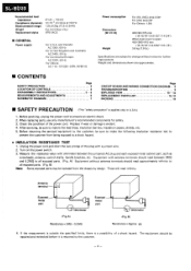
... replacing parts, use only manufacturer's recommended components for further improvement. Before returning the serviced equipment to the customer, be sure to prevent an electric shock. 2. These will read approximately infinity to the customer. -2- The equipment should read infinity. SL-BD20 ...DIAGRAM Page 2 3 3- 5 6 7 Page CIRCUIT BOARD AND WIRING CONNECTION DIAGRAM .. 8 TROUBLESHOOTING 9 EXPLODED VIEW 10 --12 REPLACEMENT PARTS LIST 12, 13 PACKING 14 ■ SAFETY PRECAUTION (This "safety precaution" is a possibility of the power cord. Check the condition...
... replacing parts, use only manufacturer's recommended components for further improvement. Before returning the serviced equipment to the customer, be sure to prevent an electric shock. 2. These will read approximately infinity to the customer. -2- The equipment should read infinity. SL-BD20 ...DIAGRAM Page 2 3 3- 5 6 7 Page CIRCUIT BOARD AND WIRING CONNECTION DIAGRAM .. 8 TROUBLESHOOTING 9 EXPLODED VIEW 10 --12 REPLACEMENT PARTS LIST 12, 13 PACKING 14 ■ SAFETY PRECAUTION (This "safety precaution" is a possibility of the power cord. Check the condition...

Service Manual
Page 5
.... 2. Remove the cueing cam. Motor Remove in the direction of the tonearm becomes too short, or if the cueing cam is replaced, apply silicon oil (Part No. Ref. To remove the PU fixing plate, remove the 2 setscrews (0, 0). Push the pin with a driver. 2. Pin -
.... 2. Remove the cueing cam. Motor Remove in the direction of the tonearm becomes too short, or if the cueing cam is replaced, apply silicon oil (Part No. Ref. To remove the PU fixing plate, remove the 2 setscrews (0, 0). Push the pin with a driver. 2. Pin -
Service Manual
Page 7
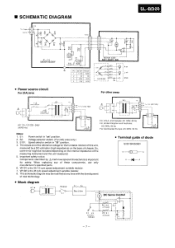
• SCHEMATIC DIAGRAM SL-BD20 FC2 To Power source 2 4,4 „j,1 A D A 03 zD ''oc zD 01- 04 SVDISR 35200V FCIOI O 2 2 8 ,j2 3 3 M 4 4 00 rest 2 4 3 26 33 45 MOTOR ASSY SM I LB02O-... switch. (For [XA] area only.) 3. Important safety notice: Components identified by a DC voltmeter (high impedance) on the basis of these components, use only manufacturer's specified parts. 6. VR102 is the 33-1/3 rpm speed adjustment variable resistor. 7. So, some error might be modified at any of chassis. D4 Rectifier M DC Servo Control 1 VR...
• SCHEMATIC DIAGRAM SL-BD20 FC2 To Power source 2 4,4 „j,1 A D A 03 zD ''oc zD 01- 04 SVDISR 35200V FCIOI O 2 2 8 ,j2 3 3 M 4 4 00 rest 2 4 3 26 33 45 MOTOR ASSY SM I LB02O-... switch. (For [XA] area only.) 3. Important safety notice: Components identified by a DC voltmeter (high impedance) on the basis of these components, use only manufacturer's specified parts. 6. VR102 is the 33-1/3 rpm speed adjustment variable resistor. 7. So, some error might be modified at any of chassis. D4 Rectifier M DC Servo Control 1 VR...
Service Manual
Page 11
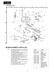
SL-BD20 • Mechanism parts 1 2 3 66 52 65 O A O ,56 O ittio O ,53 63 0O 4 56 58 56 57 RZZOL07 B RZZOLO5 RZZOL05 55 C 62 61 D 5 RZZOL05 5 67 SZZOLI I RZZOL05 56 54 RZZOLO5 51 -RZZOL05 SZZOLI I ■ REPLACEMENT PARTS LIST Notes: 1. Parts.... Italy. Important safety notice: Components identified by mark have special characteristics important for parts orders. 2. The "C)" mark is service standard parts and may differ from production parts. 7. Canada. When replacing any of description stand for all areas. 6. Belgium. Australia. ...
SL-BD20 • Mechanism parts 1 2 3 66 52 65 O A O ,56 O ittio O ,53 63 0O 4 56 58 56 57 RZZOL07 B RZZOLO5 RZZOL05 55 C 62 61 D 5 RZZOL05 5 67 SZZOLI I RZZOL05 56 54 RZZOLO5 51 -RZZOL05 SZZOLI I ■ REPLACEMENT PARTS LIST Notes: 1. Parts.... Italy. Important safety notice: Components identified by mark have special characteristics important for parts orders. 2. The "C)" mark is service standard parts and may differ from production parts. 7. Canada. When replacing any of description stand for all areas. 6. Belgium. Australia. ...

Service Manual
Page 12
... Plate, Drive (1) Spring, Drive Plate (1) Pin (5) Switch Lever (A) (1) Switch Lever (B) (1) Switch Lever (C) (1) Spring (1) Ref. Part. No. No. Part. No. 13 [M, MC] 13 [other] SGXB120 SGXB70 14 0 14 ® [M, MC] 14 ® [other] SFKTBD2N01 SFKTBD2N01 SBCB30-...other ] SFKTBD2N03 SFKTBD2N03 SBCB70-0C Knob, Speed Selector (1) Knob, Speed Selector (1) Knob, Speed Selector (1) Ref. SL-BD20 Rel. No. Part. No. No. 61 SFUMZ15R52 62 SFQSZ15R51 63 SFUGZ15R51 64 SFURZ15R52 65 SFURZ15R51 66 SFUMZ15R61 67 SHRB11 68 SFOHZ15R63 Description ...
... Plate, Drive (1) Spring, Drive Plate (1) Pin (5) Switch Lever (A) (1) Switch Lever (B) (1) Switch Lever (C) (1) Spring (1) Ref. Part. No. No. Part. No. 13 [M, MC] 13 [other] SGXB120 SGXB70 14 0 14 ® [M, MC] 14 ® [other] SFKTBD2N01 SFKTBD2N01 SBCB30-...other ] SFKTBD2N03 SFKTBD2N03 SBCB70-0C Knob, Speed Selector (1) Knob, Speed Selector (1) Knob, Speed Selector (1) Ref. SL-BD20 Rel. No. Part. No. No. 61 SFUMZ15R52 62 SFQSZ15R51 63 SFUGZ15R51 64 SFURZ15R52 65 SFURZ15R51 66 SFUMZ15R61 67 SHRB11 68 SFOHZ15R63 Description ...
