
Service Manual
Page 1
...") 230 mm (9-1/16") Tracking error angle: Effective mass: Stylus pressure: Applicable cartridge weight: Phono cable capacitance: Within 2°32' at outer groove of 30 cm (12") disc 13.5 g (including cartridge) 1.25 g (Fixed) 6g 90 pF ■ CARTRIDGE SECTION (Except for U.S.A. P.O. Belgium. SPECIFICATIONS ■ TURNTABLE SECTION Type: Features: Drive method: Motor: Drive control method: Turntable platter: Turntable speeds: Wow and flutter...
...") 230 mm (9-1/16") Tracking error angle: Effective mass: Stylus pressure: Applicable cartridge weight: Phono cable capacitance: Within 2°32' at outer groove of 30 cm (12") disc 13.5 g (including cartridge) 1.25 g (Fixed) 6g 90 pF ■ CARTRIDGE SECTION (Except for U.S.A. P.O. Belgium. SPECIFICATIONS ■ TURNTABLE SECTION Type: Features: Drive method: Motor: Drive control method: Turntable platter: Turntable speeds: Wow and flutter...
Service Manual
Page 2
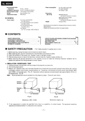
... is open: 430X360X410 mm (16-15/16"X14-5/32"X16-1/8") 3.6 kg (7.9 lb.) Specifications are approximate. ■ CONTENTS SAFETY PRECAUTION LOCATION OF CONTROLS DISASSEMBLY INSTRUCTIONS MEASUREMENTS AND ADJUSTMENTS SCHEMATIC DIAGRAM Page 2 3 3- 5 6 7 Page CIRCUIT BOARD AND WIRING CONNECTION DIAGRAM .. 8 TROUBLESHOOTING 9 EXPLODED VIEW 10 --12 REPLACEMENT PARTS LIST 12, 13 PACKING 14 ■ SAFETY PRECAUTION (This "safety precaution" is evident...
... is open: 430X360X410 mm (16-15/16"X14-5/32"X16-1/8") 3.6 kg (7.9 lb.) Specifications are approximate. ■ CONTENTS SAFETY PRECAUTION LOCATION OF CONTROLS DISASSEMBLY INSTRUCTIONS MEASUREMENTS AND ADJUSTMENTS SCHEMATIC DIAGRAM Page 2 3 3- 5 6 7 Page CIRCUIT BOARD AND WIRING CONNECTION DIAGRAM .. 8 TROUBLESHOOTING 9 EXPLODED VIEW 10 --12 REPLACEMENT PARTS LIST 12, 13 PACKING 14 ■ SAFETY PRECAUTION (This "safety precaution" is evident...
Service Manual
Page 3
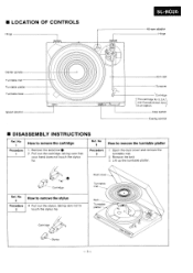
... shown here is an option. Ref3. Lift up the turntable platter. Dust cover Turntable mat Belt Turntable platter Cartridge Stylus -3- II LOCATION OF CONTROLS Hinge null O SL-BD20 45-rpm adaptor Hinge Center spindle Turntable mat Turntable platter Turntable base Speed selector Arm rest Tonearm Cartridge * The cartridge for U.S.A. Stop switch Cueing control • DISASSEMBLY INSTRUCTIONS Ref. Cartridge Ref. Open the dust cover and remove the...
... shown here is an option. Ref3. Lift up the turntable platter. Dust cover Turntable mat Belt Turntable platter Cartridge Stylus -3- II LOCATION OF CONTROLS Hinge null O SL-BD20 45-rpm adaptor Hinge Center spindle Turntable mat Turntable platter Turntable base Speed selector Arm rest Tonearm Cartridge * The cartridge for U.S.A. Stop switch Cueing control • DISASSEMBLY INSTRUCTIONS Ref. Cartridge Ref. Open the dust cover and remove the...
Service Manual
Page 4
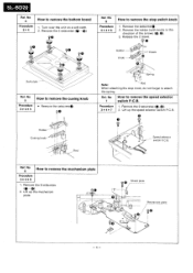
... (0 - 0) 0 i.O 4 v© © -.. Remove the holder (with knob) in the direction of the arrows (0, ID). 3. SL-BD20 Ref4. No 5 Procedure 3 0 4 0 5 How to remove the cueing knob • Remove the setscrew 00 Holder Cueing knob Rod Spring... the 2 setscrews (O, 0). 3 0 4 0 7 2. Remove the 6 setscrews 2. Ref. Procedure 1. Remove the setscrew°. 2. No How to remove the mechanism plate (0-0). 1. Turn over the unit on a soft cloth. 2. Release the 2 claws. 0 Holder Knob Claws Soft cloth - Ref. No How to attach the spring. Lift up the mechanism...
... (0 - 0) 0 i.O 4 v© © -.. Remove the holder (with knob) in the direction of the arrows (0, ID). 3. SL-BD20 Ref4. No 5 Procedure 3 0 4 0 5 How to remove the cueing knob • Remove the setscrew 00 Holder Cueing knob Rod Spring... the 2 setscrews (O, 0). 3 0 4 0 7 2. Remove the 6 setscrews 2. Ref. Procedure 1. Remove the setscrew°. 2. No How to remove the mechanism plate (0-0). 1. Turn over the unit on a soft cloth. 2. Release the 2 claws. 0 Holder Knob Claws Soft cloth - Ref. No How to attach the spring. Lift up the mechanism...

Service Manual
Page 5
To remove the tonearm, remove the 2 setscrews (0 0). 4. Apply silicon oil to remove the turntable drive motor 1. Pin - Cueing cam -- Apply silicon oil Ref. No 11 Procedure 3 0 4 0 ... to the following procedure. 1. No 9 Procedure 3040819 How to remove the cueing cam Procedure 30408110 1. Push the pin with a driver. 2. Remove the pin and spring. 3. Unsolder the 5 PU lead wires from cabinet. To remove the PU fixing plate, remove... cueing time of the tonearm becomes too short, or if the cueing cam is replaced, apply silicon oil (Part No. Remove the cueing cam. 2.
To remove the tonearm, remove the 2 setscrews (0 0). 4. Apply silicon oil to remove the turntable drive motor 1. Pin - Cueing cam -- Apply silicon oil Ref. No 11 Procedure 3 0 4 0 ... to the following procedure. 1. No 9 Procedure 3040819 How to remove the cueing cam Procedure 30408110 1. Push the pin with a driver. 2. Remove the pin and spring. 3. Unsolder the 5 PU lead wires from cabinet. To remove the PU fixing plate, remove... cueing time of the tonearm becomes too short, or if the cueing cam is replaced, apply silicon oil (Part No. Remove the cueing cam. 2.
Service Manual
Page 6
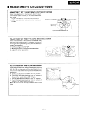
... MEASUREMENTS AND ADJUSTMENTS SL-BD20 ADJUSTMENT OF THE AUTOMATIC-RETURN POSITION Make this adjustment if the cartridge is replaced, or at any other time an adjustment is necessary because of the length of the stylus being used. (This adjustment is usually unnecessary.) 1. Set the cueing control to make the adjustment... When the turntable drive motor or the variable resistors (VR101, 102) are changed, or if the rated rotation is no automatic return. Set the speed selector switch to a position above the disc. 3. Turn VR101 with a screwdriver from the bottom of the set to the rated...
... MEASUREMENTS AND ADJUSTMENTS SL-BD20 ADJUSTMENT OF THE AUTOMATIC-RETURN POSITION Make this adjustment if the cartridge is replaced, or at any other time an adjustment is necessary because of the length of the stylus being used. (This adjustment is usually unnecessary.) 1. Set the cueing control to make the adjustment... When the turntable drive motor or the variable resistors (VR101, 102) are changed, or if the rated rotation is no automatic return. Set the speed selector switch to a position above the disc. 3. Turn VR101 with a screwdriver from the bottom of the set to the rated...
Service Manual
Page 7
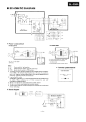
... turntable rotation of chassis. The values are of the reference voltage for safety. When replacing any time with the development of new technology. • Terminal guide of diode SVD1SR35200V K A K A • Block diagram AC IN -3 T 1 II POWER O Si D1 - D4 Rectifier M DC Servo Control ... Notes: 1. Oo 4 For U.S.A. S101: Speed selector switch in "on the internal impedance of these components, use only manufacturer's specified parts. 6. VR101 is the 45 rpm speed adjustment variable resistor. 8. S2: Voltage selector switch. (For [XA] area only.) 3. VR102 ...
... turntable rotation of chassis. The values are of the reference voltage for safety. When replacing any time with the development of new technology. • Terminal guide of diode SVD1SR35200V K A K A • Block diagram AC IN -3 T 1 II POWER O Si D1 - D4 Rectifier M DC Servo Control ... Notes: 1. Oo 4 For U.S.A. S101: Speed selector switch in "on the internal impedance of these components, use only manufacturer's specified parts. 6. VR101 is the 45 rpm speed adjustment variable resistor. 8. S2: Voltage selector switch. (For [XA] area only.) 3. VR102 ...
Service Manual
Page 8
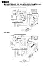
SL-BD20 • CIRCUIT BOARD AND WIRING CONNECTION DIAGRAM • For U.S.A., Canada, United Kingdom, Australia and Continental Europe. R 102 (45rpm (-33P 3 , P (SIDI DI ID2 RIO) SPEED AC IN 03 F 02 02 C3 D • A bF . D4 F0I0I ir 12 I 121 ,=132-n MOTOR / ,T I N • CI • For Others (51) POWER • VRIO2 DI D3 FC 2 •÷I - • 0-0H-0 VR 10 • 133 1 '3rp RI 01 175100-1145 04 1-0.J 30 Fs PEED AC IN VOLTAGE SELECTOR A ()TOR / / 102) FI 250V T5OrnA (S I) l POWER FC 3 I I - 8-
SL-BD20 • CIRCUIT BOARD AND WIRING CONNECTION DIAGRAM • For U.S.A., Canada, United Kingdom, Australia and Continental Europe. R 102 (45rpm (-33P 3 , P (SIDI DI ID2 RIO) SPEED AC IN 03 F 02 02 C3 D • A bF . D4 F0I0I ir 12 I 121 ,=132-n MOTOR / ,T I N • CI • For Others (51) POWER • VRIO2 DI D3 FC 2 •÷I - • 0-0H-0 VR 10 • 133 1 '3rp RI 01 175100-1145 04 1-0.J 30 Fs PEED AC IN VOLTAGE SELECTOR A ()TOR / / 102) FI 250V T5OrnA (S I) l POWER FC 3 I I - 8-

Service Manual
Page 9
... or cartridge. T1 (Power transformer) S1 (Power switch) D1-D4 (Rectifier) defective Motor ass'y VR101, 102 5101 8101, 102 }defective AC power plug is set over the turntable capstan? Turntable does not rotate. DC voltage at output pin plug (left and right channels). 0- Power source ... co (open) Check if opened circuit at pin plug or lug terminal or connector or cartridge. 500-600f2 ► Check if sequently connected to an AC wall socket. Set the belt correctly. Connect the AC power plug to amplifier or check amplifier. ■ TROUBLESHOOTING No sound comes out...
... or cartridge. T1 (Power transformer) S1 (Power switch) D1-D4 (Rectifier) defective Motor ass'y VR101, 102 5101 8101, 102 }defective AC power plug is set over the turntable capstan? Turntable does not rotate. DC voltage at output pin plug (left and right channels). 0- Power source ... co (open) Check if opened circuit at pin plug or lug terminal or connector or cartridge. 500-600f2 ► Check if sequently connected to an AC wall socket. Set the belt correctly. Connect the AC power plug to amplifier or check amplifier. ■ TROUBLESHOOTING No sound comes out...
Service Manual
Page 11
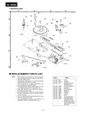
SL-BD20 • Mechanism parts 1 2 3 66 52 65 O A O ,56 O ittio O ,53 63 0O 4 56 58 56 57 RZZOL07 B RZZOLO5 RZZOL05 55 C 62 61 D 5 RZZOL05 5 67 SZZOLI I RZZOL05 56 54 RZZOLO5 51 -RZZOL05 SZZOLI I ■ REPLACEMENT PARTS LIST Notes: 1. Parts other than ®- The parenthesized numbers... per set. Parts without these components, use this part number for silver type only. 4. F.R. France. Please use only manufacturer's specified parts. 3. ®-marked partsare used for black type only, while O-marked parts are used for parts orders. 2. When replacing any ...
SL-BD20 • Mechanism parts 1 2 3 66 52 65 O A O ,56 O ittio O ,53 63 0O 4 56 58 56 57 RZZOL07 B RZZOLO5 RZZOL05 55 C 62 61 D 5 RZZOL05 5 67 SZZOLI I RZZOL05 56 54 RZZOLO5 51 -RZZOL05 SZZOLI I ■ REPLACEMENT PARTS LIST Notes: 1. Parts other than ®- The parenthesized numbers... per set. Parts without these components, use this part number for silver type only. 4. F.R. France. Please use only manufacturer's specified parts. 3. ®-marked partsare used for black type only, while O-marked parts are used for parts orders. 2. When replacing any ...

Service Manual
Page 12
...Power Source Power Source Power Source Power Source SWITCHES S1 SFDSD72R01 S2 [XA] ,1 SFDSHXW02067 only S101 SFDSHSW0834 Power Voltage Selector Speed Selector FUSE F1 [XA] only XBA2C005T1B 250V, T50mA CABINET AND CHASSIS PARTS 1 SFADZ15R01 Dust Cover (1) 2 SFGZD04N01 Rubber Cushion, Dust Cover (2) 3 SFTGB93M01 Turntable Mat (1) 4 SFTEB83M01 Turntable (1) 5 SJY90080-1 Belt... 28 ® SKMB130-0K Cover (1) TONEARM PARTS 31 SFABSA Tonearm (1) 32 EPC-P24S *Cartridge (1) [except] LM, Mcj 33 EPS-P24CS *Stylus (1) [except LM, MCJ 34 SFCNC05101 Cover ...
...Power Source Power Source Power Source Power Source SWITCHES S1 SFDSD72R01 S2 [XA] ,1 SFDSHXW02067 only S101 SFDSHSW0834 Power Voltage Selector Speed Selector FUSE F1 [XA] only XBA2C005T1B 250V, T50mA CABINET AND CHASSIS PARTS 1 SFADZ15R01 Dust Cover (1) 2 SFGZD04N01 Rubber Cushion, Dust Cover (2) 3 SFTGB93M01 Turntable Mat (1) 4 SFTEB83M01 Turntable (1) 5 SJY90080-1 Belt... 28 ® SKMB130-0K Cover (1) TONEARM PARTS 31 SFABSA Tonearm (1) 32 EPC-P24S *Cartridge (1) [except] LM, Mcj 33 EPS-P24CS *Stylus (1) [except LM, MCJ 34 SFCNC05101 Cover ...
Service Manual
Page 13
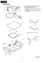
... flap "a" and then flap "b", and staple. Fold the flaps according to right and attach (2 Attach the pad. Printed in Japan 860212000 C) HS/HY SL-BD20 ■ PACKING P4 Turn to the line marks. 3. Place the unit (with adhesive tape. • Use gum tape or adhesive cloth tape of 50mm wide at least...
... flap "a" and then flap "b", and staple. Fold the flaps according to right and attach (2 Attach the pad. Printed in Japan 860212000 C) HS/HY SL-BD20 ■ PACKING P4 Turn to the line marks. 3. Place the unit (with adhesive tape. • Use gum tape or adhesive cloth tape of 50mm wide at least...

