Operating Instructions
Page 1
Please keep this product, please read these instructions completely. PP RQT7018-Y Turntable System Operating Instructions Model No. SL-1200MK5 SL-1210MK5 SL-1200MK5 Before connecting, operating or adjusting this manual for future reference.
Please keep this product, please read these instructions completely. PP RQT7018-Y Turntable System Operating Instructions Model No. SL-1200MK5 SL-1210MK5 SL-1200MK5 Before connecting, operating or adjusting this manual for future reference.
Operating Instructions
Page 2
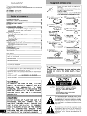
... the dust cover 7 Playing records 8 Adjustments while using the unit 9 Pitch control 9 Adjusting the turntable brake speed 9 Maintenance 10 Product service 10 Troubleshooting guide 11 Specifications 11 User memo: DATE OF PURCHASE DEALER NAME DEALER ADDRESS TELEPHONE NUMBER The model number and serial number of this product. Turntable 1pc. (SFTE172-01Z1) Balance weight ....... 1pc. (SFPWG17201K) Turntable mat .......... 1pc. (RGS0008) Disc slip sheet set for cartridge 1 •Nuts...
... the dust cover 7 Playing records 8 Adjustments while using the unit 9 Pitch control 9 Adjusting the turntable brake speed 9 Maintenance 10 Product service 10 Troubleshooting guide 11 Specifications 11 User memo: DATE OF PURCHASE DEALER NAME DEALER ADDRESS TELEPHONE NUMBER The model number and serial number of this product. Turntable 1pc. (SFTE172-01Z1) Balance weight ....... 1pc. (SFPWG17201K) Turntable mat .......... 1pc. (RGS0008) Disc slip sheet set for cartridge 1 •Nuts...

Operating Instructions
Page 3
... electrician for replacement of the obsolete outlet. 10) Protect the power cord from being walked on , the user is connected. ¡Consult the dealer or an experienced radio/TV technician for help. Operation is subject to radio communications. Follow the safety instructions on a circuit different from tip-over. 13) Unplug this device. Install in accordance...
... electrician for replacement of the obsolete outlet. 10) Protect the power cord from being walked on , the user is connected. ¡Consult the dealer or an experienced radio/TV technician for help. Operation is subject to radio communications. Follow the safety instructions on a circuit different from tip-over. 13) Unplug this device. Install in accordance...
Operating Instructions
Page 4
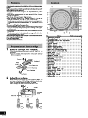
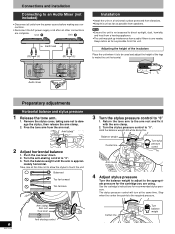
... large insulating legs. Name Reference page(s) EP record adaptor 8 Turntable base 4 Turntable mat (Or disc slip sheet 5 Turntable 5 Center spindle 5 Strobe mirrors 9 Power switch (power 8 Strobe light, pilot lamp 8 Start-stop button (start-stop 8 Speed select buttons (33, 45 8 Shell stand 4 Arm-height control 7 Balance weight 5 Stylus pressure control 6 Arm lock 7 Anti-skating control 6 Cue lever 6 Arm clamp 6 Arm rest...
... large insulating legs. Name Reference page(s) EP record adaptor 8 Turntable base 4 Turntable mat (Or disc slip sheet 5 Turntable 5 Center spindle 5 Strobe mirrors 9 Power switch (power 8 Strobe light, pilot lamp 8 Start-stop button (start-stop 8 Speed select buttons (33, 45 8 Shell stand 4 Arm-height control 7 Balance weight 5 Stylus pressure control 6 Arm lock 7 Anti-skating control 6 Cue lever 6 Arm clamp 6 Arm rest...
Operating Instructions
Page 6
... the unit horizontal. ;; Balanced Too far forward Too far back 3 Turn the stylus pressure control to the arm rest and fix it is approxi- Return the tone arm to "0" 1. See the cartridge's instructions for the cartridge you are complete. Free the tone arm from this . Arm clamp...lever down. 2. Balance weight Center line Turn stylus pressure control Arm clamp 4 Adjust stylus pressure Turn the balance weight to adjust to direct sunlight, dust, humidity, and heat from a heating appliance. •This unit may pick up interference from speakers. •Ensure the unit is not ...
... the unit horizontal. ;; Balanced Too far forward Too far back 3 Turn the stylus pressure control to the arm rest and fix it is approxi- Return the tone arm to "0" 1. See the cartridge's instructions for the cartridge you are complete. Free the tone arm from this . Arm clamp...lever down. 2. Balance weight Center line Turn stylus pressure control Arm clamp 4 Adjust stylus pressure Turn the balance weight to adjust to direct sunlight, dust, humidity, and heat from a heating appliance. •This unit may pick up interference from speakers. •Ensure the unit is not ...

Operating Instructions
Page 7
... balance weight setting for your cartridge, rest the stylus on a record and adjust the height control until the tone arm and record are marked on the turntable. 2. Release the arm lock. 1 Released 2. Armlift height Preparation 1. Make this adjustment only if the cartridge you are using the chart below as the stylus pressure control when playing normal music. Turn the stylus pressure control dial to...
... balance weight setting for your cartridge, rest the stylus on a record and adjust the height control until the tone arm and record are marked on the turntable. 2. Release the arm lock. 1 Released 2. Armlift height Preparation 1. Make this adjustment only if the cartridge you are using the chart below as the stylus pressure control when playing normal music. Turn the stylus pressure control dial to...
Operating Instructions
Page 8
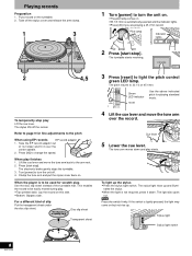
...records EP record adaptor 1. Press the switch firmly. Playing records Preparation 1. The stylus lifts off on . Take the EP record adaptor out of slip Put the transparent sheet under the disc slip sheet. When play Lift the cue lever. Disc slip sheet Transparent sheet 1 Turn [power] to 33 1/3 or 45 r/min. off the record. The turntable... its holder and fit it down and play starts. Refer to page 9 for fine adjustments to light the pitch control green LED lamp. nates the stylus. •When the light is to be used for playing standard music. 4 Lift the cue lever...
...records EP record adaptor 1. Press the switch firmly. Playing records Preparation 1. The stylus lifts off on . Take the EP record adaptor out of slip Put the transparent sheet under the disc slip sheet. When play Lift the cue lever. Disc slip sheet Transparent sheet 1 Turn [power] to 33 1/3 or 45 r/min. off the record. The turntable... its holder and fit it down and play starts. Refer to page 9 for fine adjustments to light the pitch control green LED lamp. nates the stylus. •When the light is to be used for playing standard music. 4 Lift the cue lever...
Operating Instructions
Page 9
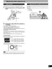
... replacing the pitch control slider. Use a small screwdriver in pitch when stationary They are lit by pressing [start-stop S BRAKE F reset 2 Slide [pitch adj.] while the turntable is revolving. The green LED indicator lights and the pitch immediately returns to the set ...power Read the pitch control slider replacement instructions that comes with [pitch adj.]. Press [reset] again and pitch returns to the preset value Press [reset]. Adjustments while using the unit Pitch control Fine adjustment to the number of revolutions per minute. 1 Press [reset] to turn off on the turntable...
... replacing the pitch control slider. Use a small screwdriver in pitch when stationary They are lit by pressing [start-stop S BRAKE F reset 2 Slide [pitch adj.] while the turntable is revolving. The green LED indicator lights and the pitch immediately returns to the set ...power Read the pitch control slider replacement instructions that comes with [pitch adj.]. Press [reset] again and pitch returns to the preset value Press [reset]. Adjustments while using the unit Pitch control Fine adjustment to the number of revolutions per minute. 1 Press [reset] to turn off on the turntable...
Operating Instructions
Page 10
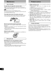
... while playing a record. Use a soft cloth. Use SFW0010 oil (not included). Thoroughly clean dust off before fitting or removing the head shell. •Damage to your records clean. Oil Product service 1. Safety check-After repairs or service, ask the servicer to perform safety checks to clean the stylus. Customer Care Centre at 1800-211-7262, or e-mail consumerproducts@panasonic...
... while playing a record. Use a soft cloth. Use SFW0010 oil (not included). Thoroughly clean dust off before fitting or removing the head shell. •Damage to your records clean. Oil Product service 1. Safety check-After repairs or service, ask the servicer to perform safety checks to clean the stylus. Customer Care Centre at 1800-211-7262, or e-mail consumerproducts@panasonic...

Operating Instructions
Page 11
... cm (12") record) Within 0° 32' (at 1-800-211-7262, or e-mail consumerproducts@panasonic.com, or the website (http://www.panasonic.com). Suggested remedy Plug the cord in ? PHONO terminals correct? cable? Troubleshooting guide Before requesting service, make the below checks. Problem No power. Reference page(s) 5 There is correctly connected. 5 Specifications Turntable section Type Quartz direct drive Manual turntable Drive method Direct...
... cm (12") record) Within 0° 32' (at 1-800-211-7262, or e-mail consumerproducts@panasonic.com, or the website (http://www.panasonic.com). Suggested remedy Plug the cord in ? PHONO terminals correct? cable? Troubleshooting guide Before requesting service, make the below checks. Problem No power. Reference page(s) 5 There is correctly connected. 5 Specifications Turntable section Type Quartz direct drive Manual turntable Drive method Direct...

Service Manual
Page 1
...in Italy. South America. * [PA] is available in F .R. C Please use this manual together with the service manual for black type of record, cartridge or tonearm, but including platter. Measured by obtaining signal from standstil l to 33-1/3 rpm ...DAD84040076S0 Service Manual Turntable System SL-1200M K2 [M], [MC], [E], [EK], [XL], [EG], [EB], [EH], [EF], [Ei], [XA], [PA], [PE], [PC] SL-1210M K2 -'4•0 0 1, 4-610S-6 F-dy-N- ORDER NO. " [PC] is the model for Model No. English Specifications Specifications are approximate. New Jersey 07094 Panasonic Hawaii...
...in Italy. South America. * [PA] is available in F .R. C Please use this manual together with the service manual for black type of record, cartridge or tonearm, but including platter. Measured by obtaining signal from standstil l to 33-1/3 rpm ...DAD84040076S0 Service Manual Turntable System SL-1200M K2 [M], [MC], [E], [EK], [XL], [EG], [EB], [EH], [EF], [Ei], [XA], [PA], [PE], [PC] SL-1210M K2 -'4•0 0 1, 4-610S-6 F-dy-N- ORDER NO. " [PC] is the model for Model No. English Specifications Specifications are approximate. New Jersey 07094 Panasonic Hawaii...

Service Manual
Page 2
...carton box. * This supplement service manual contains the bottom plate disassembly procedure, change set . Turn over the body on page 8. 0 Ct Name plate MODEL SL-1200MK2-A Serial No. It is discriminated from before-change part No., circuit diagram, P.C.B....turntable mat and turntable. 2. Insulator x 4 1. Also, check that the present change is indicated in the sirial No. and block diagrams. The other contents are the same as for the service manual of SL-1200MK2/1210MK2 already issued. * Sets with cartridge (EPC-207C) are included in those for same areas. * Since the power...
...carton box. * This supplement service manual contains the bottom plate disassembly procedure, change set . Turn over the body on page 8. 0 Ct Name plate MODEL SL-1200MK2-A Serial No. It is discriminated from before-change part No., circuit diagram, P.C.B....turntable mat and turntable. 2. Insulator x 4 1. Also, check that the present change is indicated in the sirial No. and block diagrams. The other contents are the same as for the service manual of SL-1200MK2/1210MK2 already issued. * Sets with cartridge (EPC-207C) are included in those for same areas. * Since the power...

Service Manual
Page 3
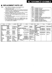
...parts list mentions only the difference between before -change of the hinge case. The "C)" mark is available in European Military. * [PC] is service standard parts and may differ from production parts...marked parts are used for before and after change sets. 0 0 0 0 Hinge case 41 Bottom base • REPLACEMENT PARTS LIST Notes:...Control Adjustment, aft (B) Pitch Control Start/Stop Power Power Source Power Source Power Source Per Set Remarks (Pcs.) 1 1 1 A, 2 4 1 1 1 1 1 1 1 1 1 Ai Remove the 4 setscrews (Fig. 2 : 0) of SL-1200MK2/1210MK2. ® 2. -marked parts...
...parts list mentions only the difference between before -change of the hinge case. The "C)" mark is available in European Military. * [PC] is service standard parts and may differ from production parts...marked parts are used for before and after change sets. 0 0 0 0 Hinge case 41 Bottom base • REPLACEMENT PARTS LIST Notes:...Control Adjustment, aft (B) Pitch Control Start/Stop Power Power Source Power Source Power Source Per Set Remarks (Pcs.) 1 1 1 A, 2 4 1 1 1 1 1 1 1 1 1 Ai Remove the 4 setscrews (Fig. 2 : 0) of SL-1200MK2/1210MK2. ® 2. -marked parts...
Service Manual
Page 4
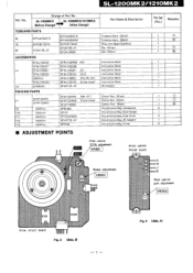
... POINTS Part Name & Description Tonearm Ass'y (Silver) Tonearm Ass'y (Black) Ring, Arm Base Operation Cap (Silver) Cap (Black) Instruction Book Instruction Book Instruction Book Instruction Book Instruction Book Instruction Book ...control ±0% adjustment VR30I Pitch control Circuit board °e() 0:4 • O Brake adjustment VR2OI O =6 Per Set Remarks (Pas.) 1 0 1 0 1 1 0 1 0 1 1 1 1 1 1 1 0 1 0 1 0 2 1 3 2 6 7 Pitch control gain adjustment VR302 ICIOI IC20I Drive circuit board ME II Fig. 3 (Abb. 3) - 7- 0 0 Fig. 4 (Abb. 4) Change of Part No. No. SL...
... POINTS Part Name & Description Tonearm Ass'y (Silver) Tonearm Ass'y (Black) Ring, Arm Base Operation Cap (Silver) Cap (Black) Instruction Book Instruction Book Instruction Book Instruction Book Instruction Book Instruction Book ...control ±0% adjustment VR30I Pitch control Circuit board °e() 0:4 • O Brake adjustment VR2OI O =6 Per Set Remarks (Pas.) 1 0 1 0 1 1 0 1 0 1 1 1 1 1 1 1 0 1 0 1 0 2 1 3 2 6 7 Pitch control gain adjustment VR302 ICIOI IC20I Drive circuit board ME II Fig. 3 (Abb. 3) - 7- 0 0 Fig. 4 (Abb. 4) Change of Part No. No. SL...
Service Manual
Page 5
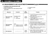
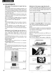
...Earth point VR301 (Fig..3) 1. Connect the frequency counter and turn the power supply ON. 2. CN102 terminal ® . (-) - CN102 terminal ® VR302 (Fig. 4/ 1. Remove the bottom cover (when adjusting the pitch control gain). 3. Adjust VR301 so that the rotation at 33 ... the stop button. SL-1200MK2/1210MK2 • MEASUREMENTS AND ADJUSTMENTS English • Conditions of drive P.C.B. 3. Remove the panel cover. 2. Tester Adjustment Connection Parts adjusted Procedure 1 Pitch control ± 0% adjustment Frequency counter (+) - Set the pitch control knob to "0". 2....
...Earth point VR301 (Fig..3) 1. Connect the frequency counter and turn the power supply ON. 2. CN102 terminal ® . (-) - CN102 terminal ® VR302 (Fig. 4/ 1. Remove the bottom cover (when adjusting the pitch control gain). 3. Adjust VR301 so that the rotation at 33 ... the stop button. SL-1200MK2/1210MK2 • MEASUREMENTS AND ADJUSTMENTS English • Conditions of drive P.C.B. 3. Remove the panel cover. 2. Tester Adjustment Connection Parts adjusted Procedure 1 Pitch control ± 0% adjustment Frequency counter (+) - Set the pitch control knob to "0". 2....

Service Manual
Page 7
L-1200MK2 0 Fig. 4 Fig. 7 Lampcaset Fig. 5 Fig. 6 ■ PARTS IDENTIFICATION Hinge 45-rpm adaptor Turntable base Turntable mat Arm clamp Center spindle Turntable platter Strobe dots Power switch Strobe-il l urn inato ri pilot lamp Start stop butto❑ Speed select buttons Fig. B Arm-height adjustment ring Fig. 9 Balance weight Stylus pressure ring Arm lock knob Anti-skating control knob Cueing lever Arm rest Tonearm Pitch indicator Pitch control knob Locking nut Headshell Stylus illuminator switch Stylus illuminator Fig. 10
L-1200MK2 0 Fig. 4 Fig. 7 Lampcaset Fig. 5 Fig. 6 ■ PARTS IDENTIFICATION Hinge 45-rpm adaptor Turntable base Turntable mat Arm clamp Center spindle Turntable platter Strobe dots Power switch Strobe-il l urn inato ri pilot lamp Start stop butto❑ Speed select buttons Fig. B Arm-height adjustment ring Fig. 9 Balance weight Stylus pressure ring Arm lock knob Anti-skating control knob Cueing lever Arm rest Tonearm Pitch indicator Pitch control knob Locking nut Headshell Stylus illuminator switch Stylus illuminator Fig. 10
Service Manual
Page 9
...record and stylus tip is released. Height of cartridge (mm) Scale reading on the adjust ring in 4 stages marked at the D., 1,O5. Please pup-chase original oil. (Part number... can be sure that for variable pitch control. O! appea:s strAtkmaly at the center ...turning on the indicator show approximate percentages for conventional type motors (200-500 hours). tp.pd.en ntat"wi£ty at the peripheral edge of the turntable...power, the green LED indicator is SFWO 010.) 8 m (6/18-33/64") Fig. 20 Ant screw lift bar Fig. 21 0 S0 . 0 • • es. Be sure to set...
...record and stylus tip is released. Height of cartridge (mm) Scale reading on the adjust ring in 4 stages marked at the D., 1,O5. Please pup-chase original oil. (Part number... can be sure that for variable pitch control. O! appea:s strAtkmaly at the center ...turning on the indicator show approximate percentages for conventional type motors (200-500 hours). tp.pd.en ntat"wi£ty at the peripheral edge of the turntable...power, the green LED indicator is SFWO 010.) 8 m (6/18-33/64") Fig. 20 Ant screw lift bar Fig. 21 0 S0 . 0 • • es. Be sure to set...

Service Manual
Page 10
... Germany. * IEB] is service standard parts and may differ from production parts. 4. Part No. 5.6K 6.8K 2.7K...0 ERD25FJ471 0 ERD25FJ822 6 ERD25FJ561 O ERD25FJ18I ® ERD25TJ223 0 ERD25FJ272 Z. When replacing any of these indications can be used for all area. 5. The unit capacitance ...Parts without these components use only manufacturer's specified parts. 3. K = 1000R, M = 1000kS2 6. No. Peculiarity ECEA Type 50 M Voltage Reculiarity use R47 Value R Special use this part number for safety. SL-1200MK2/1210MK2 ■ RESISTORS AND CAPACITORS Notes: 1. Part numbers...
... Germany. * IEB] is service standard parts and may differ from production parts. 4. Part No. 5.6K 6.8K 2.7K...0 ERD25FJ471 0 ERD25FJ822 6 ERD25FJ561 O ERD25FJ18I ® ERD25TJ223 0 ERD25FJ272 Z. When replacing any of these indications can be used for all area. 5. The unit capacitance ...Parts without these components use only manufacturer's specified parts. 3. K = 1000R, M = 1000kS2 6. No. Peculiarity ECEA Type 50 M Voltage Reculiarity use R47 Value R Special use this part number for safety. SL-1200MK2/1210MK2 ■ RESISTORS AND CAPACITORS Notes: 1. Part numbers...
Service Manual
Page 11
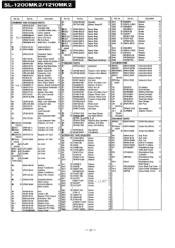
...) Pitch Control±0% AdJustment,2k0(8) Pitch Control Gain Adluslment50k01B) Pitch Control Speed Selector Stort/Stop Stylus-Illuminator Power Voltage Selector LAMP PL1 TRANSFORMER 11(m) A TI (MO) 21(0ther areas) A FUSES F1 (MC) Fl Except L for (M,MCI F2 Except A for safety. Germany. [EB1 is available in European Military. Ref. Description Ref. SL-1200MK2/1210MK2 • REPLACEMENT PARTS LIST Notes: 1. Part numbers are...
...) Pitch Control±0% AdJustment,2k0(8) Pitch Control Gain Adluslment50k01B) Pitch Control Speed Selector Stort/Stop Stylus-Illuminator Power Voltage Selector LAMP PL1 TRANSFORMER 11(m) A TI (MO) 21(0ther areas) A FUSES F1 (MC) Fl Except L for (M,MCI F2 Except A for safety. Germany. [EB1 is available in European Military. Ref. Description Ref. SL-1200MK2/1210MK2 • REPLACEMENT PARTS LIST Notes: 1. Part numbers are...
Service Manual
Page 12
... (1) Button, Speed Oh (1) Connector, 7pin (1) Spacer, Rubber (1) Ball, Switch Cam (1) Spring, Switch Cam (1) Cam, Power Switch (1) Spacer, Speed Indicator(2) Cover,Stylus Illuminator (1) Boss, Drive (1) Spring, Drive Boss (1) Pln, Lock Canceler (1) Bracket, (1) Stylus Illuminator (1) Plate, Lock Operation (1) Connector, 3pin (1) Pin, Guide (1) Spring, (1) Lock Canceler Spring, (1) Lock Operation Plate Pin, (1) Lock Operation Plate Clamper, AC Cord...
... (1) Button, Speed Oh (1) Connector, 7pin (1) Spacer, Rubber (1) Ball, Switch Cam (1) Spring, Switch Cam (1) Cam, Power Switch (1) Spacer, Speed Indicator(2) Cover,Stylus Illuminator (1) Boss, Drive (1) Spring, Drive Boss (1) Pln, Lock Canceler (1) Bracket, (1) Stylus Illuminator (1) Plate, Lock Operation (1) Connector, 3pin (1) Pin, Guide (1) Spring, (1) Lock Canceler Spring, (1) Lock Operation Plate Pin, (1) Lock Operation Plate Clamper, AC Cord...

