
Door Phone Card
Page 1
Installation Instructions Doorphone Card Model KX-TD161 Please read this manual before installing the card.
Installation Instructions Doorphone Card Model KX-TD161 Please read this manual before installing the card.

Door Phone Card
Page 2
Contents Location of the Card 3 Installation for purchasing the Panasonic Card. Thank you for the Card 5 Doorphone Card 7 2 The doorphone is an option (KX-T30865). Doorphone Card Supports 4 doorphones and 4 door openers.
Contents Location of the Card 3 Installation for purchasing the Panasonic Card. Thank you for the Card 5 Doorphone Card 7 2 The doorphone is an option (KX-T30865). Doorphone Card Supports 4 doorphones and 4 door openers.
Door Phone Card
Page 3
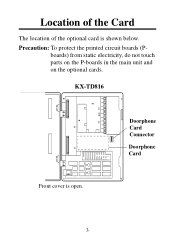
Doorphone Card Connector Doorphone Card 3 KX-TD816 Front cover is shown below. boards) from static electricity, do not touch parts on the P-boards in the main unit and on the optional cards. Precaution: To protect the printed circuit boards (P- Location of the Card The location of the optional card is open.
Doorphone Card Connector Doorphone Card 3 KX-TD816 Front cover is shown below. boards) from static electricity, do not touch parts on the P-boards in the main unit and on the optional cards. Precaution: To protect the printed circuit boards (P- Location of the Card The location of the optional card is open.
Door Phone Card
Page 4
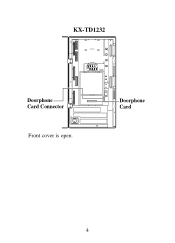
KX-TD1232 Doorphone Card Connector DOORPHONE Doorphone Card Front cover is open. 4
KX-TD1232 Doorphone Card Connector DOORPHONE Doorphone Card Front cover is open. 4
Door Phone Card
Page 5
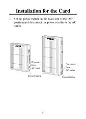
Set the power switch on the main unit to the OFF position and disconnect the power cord from AC outlet Power Switch 5 D816 DIGITAL SUPER HYBRID SYSTEM D1232 DIGITAL SUPER HYBRID SYSTEM Disconnect from Panasonic AC outlet Panasonic Power Switch Disconnect from the AC outlet. Installation for the Card 1.
Set the power switch on the main unit to the OFF position and disconnect the power cord from AC outlet Power Switch 5 D816 DIGITAL SUPER HYBRID SYSTEM D1232 DIGITAL SUPER HYBRID SYSTEM Disconnect from Panasonic AC outlet Panasonic Power Switch Disconnect from the AC outlet. Installation for the Card 1.

Door Phone Card
Page 6
2. Close the front cover and screw. 5. Loosen the two screws on the main unit to ON position. 6 A D816 DIGITAL SUPER HYBRID SYSTEM A screw D1232 DIGITAL SUPER HYBRID SYSTEM screw Panasonic screw Panasonic screw Note • The two screws are attached to the AC outlet and then set the Power Switch on the right side of the main unit and open the front cover in the direction of arrow A . To install the Doorphone Card, see page 7. 4. Connect the power cord to the front cover with springs so that they will not be lost. 3.
2. Close the front cover and screw. 5. Loosen the two screws on the main unit to ON position. 6 A D816 DIGITAL SUPER HYBRID SYSTEM A screw D1232 DIGITAL SUPER HYBRID SYSTEM screw Panasonic screw Panasonic screw Note • The two screws are attached to the AC outlet and then set the Power Switch on the right side of the main unit and open the front cover in the direction of arrow A . To install the Doorphone Card, see page 7. 4. Connect the power cord to the front cover with springs so that they will not be lost. 3.
Door Phone Card
Page 7
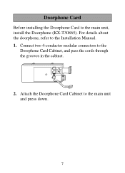
Attach the Doorphone Card Cabinet to the Doorphone Card Cabinet, and pass the cords through the grooves in the cabinet. 2. Connect two 4-conductor modular connectors to the main unit and press down. 7 Doorphone Card Before installing the Doorphone Card to the Installation Manual. 1. For details about the doorphone, refer to the main unit, install the Doorphone (KX-T30865).
Attach the Doorphone Card Cabinet to the Doorphone Card Cabinet, and pass the cords through the grooves in the cabinet. 2. Connect two 4-conductor modular connectors to the main unit and press down. 7 Doorphone Card Before installing the Doorphone Card to the Installation Manual. 1. For details about the doorphone, refer to the main unit, install the Doorphone (KX-T30865).

Door Phone Card
Page 8
KX-TD1232 KX-TD816 To Terminal Box Installation 8 Connect the cord to the Doorphone Card Connector. 3.
KX-TD1232 KX-TD816 To Terminal Box Installation 8 Connect the cord to the Doorphone Card Connector. 3.
Door Phone Card
Page 9
Wiring of the terminal box. 5. Connect the wires of doorphone 3 to the red and green screws of the Doorphone 1. Connect the Doorphone Card to the red and green screws of the terminal box. 3. Connect the wires of doorphone 2 to the yellow and black screws of the terminal box. 4. Connect the wires of doorphone 4 to the yellow and black screws of the terminal box. 9 Connect the wires of doorphone 1 to the terminal box using two 4-conductor modular connectors. 2.
Wiring of the terminal box. 5. Connect the wires of doorphone 3 to the red and green screws of the Doorphone 1. Connect the Doorphone Card to the red and green screws of the terminal box. 3. Connect the wires of doorphone 2 to the yellow and black screws of the terminal box. 4. Connect the wires of doorphone 4 to the yellow and black screws of the terminal box. 9 Connect the wires of doorphone 1 to the terminal box using two 4-conductor modular connectors. 2.
Door Phone Card
Page 10
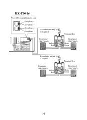
Doorphone 1 (KX-T30865) Yellow Red Panasonic Terminal Box Doorphone 4 (KX-T30865) Black Green Panasonic Terminal Box Doorphone 2 (KX-T30865) Black Green Panasonic 10 Doorphone 3 (KX-T30865) Yellow Red Panasonic 4-conductor wiring is required. KX-TD816 View of Doorphone Connector Jack Doorphone 4 Doorphone 3 Doorphone 2 Doorphone 1 4-conductor wiring is required.
Doorphone 1 (KX-T30865) Yellow Red Panasonic Terminal Box Doorphone 4 (KX-T30865) Black Green Panasonic Terminal Box Doorphone 2 (KX-T30865) Black Green Panasonic 10 Doorphone 3 (KX-T30865) Yellow Red Panasonic 4-conductor wiring is required. KX-TD816 View of Doorphone Connector Jack Doorphone 4 Doorphone 3 Doorphone 2 Doorphone 1 4-conductor wiring is required.
Door Phone Card
Page 11
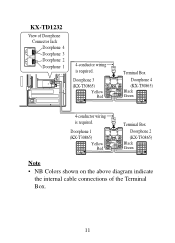
Doorphone 3 (KX-T30865) Yellow Red Panasonic Terminal Box Doorphone 4 (KX-T30865) Black Green Panasonic 4-conductor wiring is required. Doorphone 1 (KX-T30865) Yellow Red Panasonic Terminal Box Doorphone 2 (KX-T30865) Black Green Panasonic Note • NB Colors shown on the above diagram indicate the internal cable connections of Doorphone Connector Jack Doorphone 4 Doorphone 3 Doorphone 2 Doorphone 1 4-conductor wiring is required. KX-TD1232 View of the Terminal Box. 11
Doorphone 3 (KX-T30865) Yellow Red Panasonic Terminal Box Doorphone 4 (KX-T30865) Black Green Panasonic 4-conductor wiring is required. Doorphone 1 (KX-T30865) Yellow Red Panasonic Terminal Box Doorphone 2 (KX-T30865) Black Green Panasonic Note • NB Colors shown on the above diagram indicate the internal cable connections of Doorphone Connector Jack Doorphone 4 Doorphone 3 Doorphone 2 Doorphone 1 4-conductor wiring is required. KX-TD1232 View of the Terminal Box. 11

Door Phone Card
Page 12
Loosen the screws on the terminal strip. 12 Loosen the screw to remove the cover. 2. Connecting Door Openers 1.
Loosen the screws on the terminal strip. 12 Loosen the screw to remove the cover. 2. Connecting Door Openers 1.

Door Phone Card
Page 13
D=1.2 mm-2.4 mm (3/64 inch-3/32 inch) 13 Holder To door opener 4 To door opener 3 To door opener 2 To door opener 1 Note • Set the door opener paired with the doorphone. • For wiring, UL 1015, AWG 22 twisted wire or the equivalent is recommended. • The wire should be between 1.2 mm and 2.4 mm (3/64 inch and 3/32 inch) in diameter including the coating. Pass all the wires through the Holder. Insert the wires coming from the door openers into holes and tighten the screws. 3.
D=1.2 mm-2.4 mm (3/64 inch-3/32 inch) 13 Holder To door opener 4 To door opener 3 To door opener 2 To door opener 1 Note • Set the door opener paired with the doorphone. • For wiring, UL 1015, AWG 22 twisted wire or the equivalent is recommended. • The wire should be between 1.2 mm and 2.4 mm (3/64 inch and 3/32 inch) in diameter including the coating. Pass all the wires through the Holder. Insert the wires coming from the door openers into holes and tighten the screws. 3.

Door Phone Card
Page 16
... consent of Puerto Rico, Inc. Under the applicable copyright laws, this manual may not be reproduced in any form, in the United Kingdom PSQX2631ZA KA0901HK0 Panasonic Consumer Electronics Company, Division of Matsushita Electric Corporation of America One Panasonic Way, Secaucus, New Jersey 07094 www.panasonic.com Panasonic Sales Company ("PSC"), Division of Matsushita Electric of KME and its...
... consent of Puerto Rico, Inc. Under the applicable copyright laws, this manual may not be reproduced in any form, in the United Kingdom PSQX2631ZA KA0901HK0 Panasonic Consumer Electronics Company, Division of Matsushita Electric Corporation of America One Panasonic Way, Secaucus, New Jersey 07094 www.panasonic.com Panasonic Sales Company ("PSC"), Division of Matsushita Electric of KME and its...

