Operation Manual
Page 3
Operating Manual (this manual) The Operating Manual explains the part names, operations, features and maintenance of 2 manuals: the Installation Manual and the Operating Manual. Introduction About the documentation The scanner documentation consists of ...used for maintenance, by clicking the help button that appears on the software's operation screen. • You can view explanations about viewing the help for Panasonic Image Enhancement Technology (PIE) functions that are trademarks of their respective owners. Software help • You can also view the help , see "Viewing ...
Operating Manual (this manual) The Operating Manual explains the part names, operations, features and maintenance of 2 manuals: the Installation Manual and the Operating Manual. Introduction About the documentation The scanner documentation consists of ...used for maintenance, by clicking the help button that appears on the software's operation screen. • You can view explanations about viewing the help for Panasonic Image Enhancement Technology (PIE) functions that are trademarks of their respective owners. Software help • You can also view the help , see "Viewing ...
Operation Manual
Page 5
... device is likely to cause harmful interference in a commercial environment. Also, any unauthorized changes or modifications to this equipment would void the user's authority to Part 15 of the FCC Rules. These limits are designed to radio communications. Introduction Federal Communications Commission Requirements (For United States only) Note This equipment has...
... device is likely to cause harmful interference in a commercial environment. Also, any unauthorized changes or modifications to this equipment would void the user's authority to Part 15 of the FCC Rules. These limits are designed to radio communications. Introduction Federal Communications Commission Requirements (For United States only) Note This equipment has...
Operation Manual
Page 6
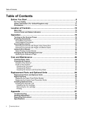
... of the Scanner ...51 Cleaning the Conveyor 53 Cleaning the Rollers ...56 Cleaning the Sensors and Scanning Glass 60 Replacement Parts and Optional Units 64 Replacement Parts and Optional Units 64 Replacing Parts ...65 Replacing the Paper Feed Roller Module 65 Replacing the Double Feed Prevention Roller 69 Installing Optional Units 74 Installing...
... of the Scanner ...51 Cleaning the Conveyor 53 Cleaning the Rollers ...56 Cleaning the Sensors and Scanning Glass 60 Replacement Parts and Optional Units 64 Replacement Parts and Optional Units 64 Replacing Parts ...65 Replacing the Paper Feed Roller Module 65 Replacing the Double Feed Prevention Roller 69 Installing Optional Units 74 Installing...

Operation Manual
Page 9
... with wet hands. Danger of the cord. Operating the contaminated unit can cause fire or electric shock. Do not alter the unit or modify any parts. Before You Start Do not attempt to repair the unit yourself. Do not drink or inhale the roller cleaning paper fluid including isopropyl alcohol. Contact...
... with wet hands. Danger of the cord. Operating the contaminated unit can cause fire or electric shock. Do not alter the unit or modify any parts. Before You Start Do not attempt to repair the unit yourself. Do not drink or inhale the roller cleaning paper fluid including isopropyl alcohol. Contact...
Operation Manual
Page 51
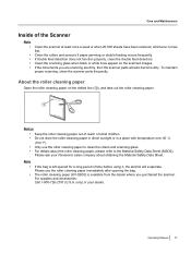
... roller cleaning paper to the Material Safety Data Sheet (MSDS). only) or your Panasonic sales company about the roller cleaning paper, please refer to clean the rollers and ...Data Sheet. If the documents you purchased the scanner. To maintain proper scanning, clean the scanner parts frequently. Operating Manual 51 Note • • If the bag is available from the dealer where... roller cleaning paper Open the roller cleaning paper on the scanned images. The roller cleaning paper (KV-SS03) is left opened for a long period of time before using it, the alcohol will ...
... roller cleaning paper to the Material Safety Data Sheet (MSDS). only) or your Panasonic sales company about the roller cleaning paper, please refer to clean the rollers and ...Data Sheet. If the documents you purchased the scanner. To maintain proper scanning, clean the scanner parts frequently. Operating Manual 51 Note • • If the bag is available from the dealer where... roller cleaning paper Open the roller cleaning paper on the scanned images. The roller cleaning paper (KV-SS03) is left opened for a long period of time before using it, the alcohol will ...
Operation Manual
Page 64
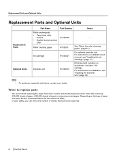
...n d O p t i Optional Units Imprinter unit o n a KV-SS021 KV-SS014 For optional imprinter unit. Includes 1 ink cartridge. i t s When to replace parts We recommend replacing the paper feed roller module and double feed prevention roller ..." (page 77). Replacement Parts and Optional Units R e p l Replacement Parts and Optional Units a c Part Name Part Number Notes e m Roller exchange kit e • Paper feed roller n module KV-SS039 - t • Double feed prevention P roller a r Replacement Parts Roller cleaning paper KV-SS03 See "About the ...
...n d O p t i Optional Units Imprinter unit o n a KV-SS021 KV-SS014 For optional imprinter unit. Includes 1 ink cartridge. i t s When to replace parts We recommend replacing the paper feed roller module and double feed prevention roller ..." (page 77). Replacement Parts and Optional Units R e p l Replacement Parts and Optional Units a c Part Name Part Number Notes e m Roller exchange kit e • Paper feed roller n module KV-SS039 - t • Double feed prevention P roller a r Replacement Parts Roller cleaning paper KV-SS03 See "About the ...
Operation Manual
Page 65
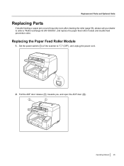
Replacing the Paper Feed Roller Module 1. Set the power switch (A) of the scanner to order a "Roller exchange kit (KV-SS039)", and replace the paper feed roller module and double feed prevention roller. Replacement Parts and Optional Units Replacing Parts If double feeding or paper jam occurs frequently even after cleaning the roller (page 56), please call your dealer to " " (OFF), and unplug the power cord. 1 2. Pull the ADF door release (A) towards you, and open the ADF door (B). 2 1 Operating Manual 65
Replacing the Paper Feed Roller Module 1. Set the power switch (A) of the scanner to order a "Roller exchange kit (KV-SS039)", and replace the paper feed roller module and double feed prevention roller. Replacement Parts and Optional Units Replacing Parts If double feeding or paper jam occurs frequently even after cleaning the roller (page 56), please call your dealer to " " (OFF), and unplug the power cord. 1 2. Pull the ADF door release (A) towards you, and open the ADF door (B). 2 1 Operating Manual 65
Operation Manual
Page 66
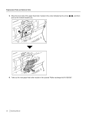
Take out the new paper feed roller module in the order indicated by the arrow (A, B), and then pull out the module towards you. 1 2 1 4. Move the lever (A) of the paper feed roller module in the optional "Roller exchange kit (KV-SS039)". 66 Operating Manual Replacement Parts and Optional Units 3.
Take out the new paper feed roller module in the order indicated by the arrow (A, B), and then pull out the module towards you. 1 2 1 4. Move the lever (A) of the paper feed roller module in the optional "Roller exchange kit (KV-SS039)". 66 Operating Manual Replacement Parts and Optional Units 3.
Operation Manual
Page 67
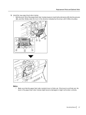
Replacement Parts and Optional Units 5. If the lever is firmly set , the lever or the paper feed roller module might become damaged or might not function correctly. Install the new paper feed roller module. • With the lever (A) of the paper feed roller module lowered, insert both protrusions (B) into the grooves (C), and then slowly raise the lever in the direction indicated by the arrow until it clicks into place. 3 2 21 3 2 3 Notice • Make sure that the paper feed roller module's lever is not firmly set . Operating Manual 67
Replacement Parts and Optional Units 5. If the lever is firmly set , the lever or the paper feed roller module might become damaged or might not function correctly. Install the new paper feed roller module. • With the lever (A) of the paper feed roller module lowered, insert both protrusions (B) into the grooves (C), and then slowly raise the lever in the direction indicated by the arrow until it clicks into place. 3 2 21 3 2 3 Notice • Make sure that the paper feed roller module's lever is not firmly set . Operating Manual 67
Operation Manual
Page 68
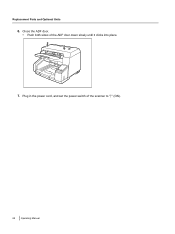
Close the ADF door. • Push both sides of the scanner to " " (ON). 68 Operating Manual Plug in the power cord, and set the power switch of the ADF door down slowly until it clicks into place. 7. Replacement Parts and Optional Units 6.
Close the ADF door. • Push both sides of the scanner to " " (ON). 68 Operating Manual Plug in the power cord, and set the power switch of the ADF door down slowly until it clicks into place. 7. Replacement Parts and Optional Units 6.
Operation Manual
Page 69
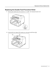
Set the power switch (A) of the scanner to " " (OFF), and unplug the power cord. 1 2. Replacement Parts and Optional Units Replacing the Double Feed Prevention Roller 1. Pull the ADF door release (A) towards you, and open the ADF door (B). 2 1 Operating Manual 69
Set the power switch (A) of the scanner to " " (OFF), and unplug the power cord. 1 2. Replacement Parts and Optional Units Replacing the Double Feed Prevention Roller 1. Pull the ADF door release (A) towards you, and open the ADF door (B). 2 1 Operating Manual 69
Operation Manual
Page 70
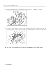
Replacement Parts and Optional Units 3. While pulling the tab (A) in the direction of the arrow. Then, pull out the right shaft (when facing it) from the notch in the optional "Roller exchange kit (KV-SS039)". 70 Operating Manual Take out the new double feed prevention roller in the roller mount. 2 1 5. Pull towards you and remove the double feed prevention roller cover by the arrow, lift the double feed prevention roller (B) in the direction indicated by using the indent (A). 1 4.
Replacement Parts and Optional Units 3. While pulling the tab (A) in the direction of the arrow. Then, pull out the right shaft (when facing it) from the notch in the optional "Roller exchange kit (KV-SS039)". 70 Operating Manual Take out the new double feed prevention roller in the roller mount. 2 1 5. Pull towards you and remove the double feed prevention roller cover by the arrow, lift the double feed prevention roller (B) in the direction indicated by using the indent (A). 1 4.
Operation Manual
Page 71
Install the new double feed prevention roller. • Align the shaft that is inserted into place. 3 1 2 2 1 Notice • After you install the double feed prevention roller, make sure that the shaft will not rotate or move. Push the shaft on the opposite side (C) until it may cause double feeding or a paper jam. If the roller is not installed correctly, it clicks into the tab, and that the shaft is shaped as indicated by A with the notch in the roller mount (B), and then insert the shaft in the notch. Replacement Parts and Optional Units 6. Operating Manual 71
Install the new double feed prevention roller. • Align the shaft that is inserted into place. 3 1 2 2 1 Notice • After you install the double feed prevention roller, make sure that the shaft will not rotate or move. Push the shaft on the opposite side (C) until it may cause double feeding or a paper jam. If the roller is not installed correctly, it clicks into the tab, and that the shaft is shaped as indicated by A with the notch in the roller mount (B), and then insert the shaft in the notch. Replacement Parts and Optional Units 6. Operating Manual 71

Operation Manual
Page 72
If the double feed prevention roller cover is closed incompletely, damage or paper jams can occur. 8. Insert the protrusion (A) of the double feed prevention roller cover into the hole on the main unit, and then push in the part of the ADF door down slowly until it clicks into place. 2 1 Notice • Make sure that the double feed prevention roller cover does not stick up. Close the ADF door. • Push both sides of the roller cover indicated by B in the direction indicated by the arrow until it clicks into place. 72 Operating Manual Replacement Parts and Optional Units 7.
If the double feed prevention roller cover is closed incompletely, damage or paper jams can occur. 8. Insert the protrusion (A) of the double feed prevention roller cover into the hole on the main unit, and then push in the part of the ADF door down slowly until it clicks into place. 2 1 Notice • Make sure that the double feed prevention roller cover does not stick up. Close the ADF door. • Push both sides of the roller cover indicated by B in the direction indicated by the arrow until it clicks into place. 72 Operating Manual Replacement Parts and Optional Units 7.

Operation Manual
Page 73
Plug in the window, click the [Clear Counter] button for "After Replace Roller" to reset the counter to 0. • For details, refer to " " (ON). 10. Operating Manual 73 Reset the roller replacing counter in User Utility to 0. • Start User Utility, and in the power cord, and set the power switch of the scanner to the User Utility help. Replacement Parts and Optional Units 9.
Plug in the window, click the [Clear Counter] button for "After Replace Roller" to reset the counter to 0. • For details, refer to " " (ON). 10. Operating Manual 73 Reset the roller replacing counter in User Utility to 0. • Start User Utility, and in the power cord, and set the power switch of the scanner to the User Utility help. Replacement Parts and Optional Units 9.
Operation Manual
Page 74
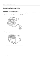
Replacement Parts and Optional Units Installing Optional Units Installing the Imprinter Unit The imprinter prints on the face of the scanner to " " (OFF). 1 2. Open the imprinter door. 74 Operating Manual Set the power switch (A) of the document before scanning. The printed material will also be scanned. 1.
Replacement Parts and Optional Units Installing Optional Units Installing the Imprinter Unit The imprinter prints on the face of the scanner to " " (OFF). 1 2. Open the imprinter door. 74 Operating Manual Set the power switch (A) of the document before scanning. The printed material will also be scanned. 1.

Operation Manual
Page 75
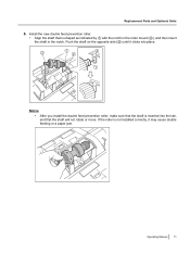
Replacement Parts and Optional Units Notice • Be sure to correctly match the rib with the slot prior to inserting the connector. 4. 3. While keeping the direction of the imprinter as shown in the diagram below, insert the pins (A) on both sides into the guides, and insert the pins (B) on both sides into the guides until they are locked by the springs (C). 1 2 1 2 3 Operating Manual 75 Connect the cable.
Replacement Parts and Optional Units Notice • Be sure to correctly match the rib with the slot prior to inserting the connector. 4. 3. While keeping the direction of the imprinter as shown in the diagram below, insert the pins (A) on both sides into the guides, and insert the pins (B) on both sides into the guides until they are locked by the springs (C). 1 2 1 2 3 Operating Manual 75 Connect the cable.

Operation Manual
Page 76
Replacement Parts and Optional Units 5. Note • For details on installing an ink cartridge, refer to " " (ON). Set the power switch of the scanner to "Installing the Ink Cartridge" (page 77). 76 Operating Manual Close the imprinter door. 6.
Replacement Parts and Optional Units 5. Note • For details on installing an ink cartridge, refer to " " (ON). Set the power switch of the scanner to "Installing the Ink Cartridge" (page 77). 76 Operating Manual Close the imprinter door. 6.
Operation Manual
Page 77
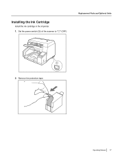
Operating Manual 77 Set the power switch (A) of the scanner to " " (OFF). Remove the protective tape. Installing the Ink Cartridge Install the ink cartridge in the imprinter. 1. Replacement Parts and Optional Units 1 2.
Operating Manual 77 Set the power switch (A) of the scanner to " " (OFF). Remove the protective tape. Installing the Ink Cartridge Install the ink cartridge in the imprinter. 1. Replacement Parts and Optional Units 1 2.
Operation Manual
Page 78
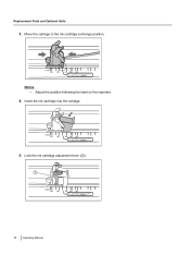
Notice • Adjust the position following the label on the imprinter. 4. Move the carriage to the ink cartridge exchange position. Insert the ink cartridge into the carriage. 5. Lock the ink cartridge adjustment lever (A). 1 78 Operating Manual Replacement Parts and Optional Units 3.
Notice • Adjust the position following the label on the imprinter. 4. Move the carriage to the ink cartridge exchange position. Insert the ink cartridge into the carriage. 5. Lock the ink cartridge adjustment lever (A). 1 78 Operating Manual Replacement Parts and Optional Units 3.