Installation Instructions
Page 1
... Construction) 7 Maintenance 7-8 Practical guide to comply with instructions could result in personal injury and/or property damage. Failure to installation 8 Product Service 8 INSTALLATION INSTRUCTIONS Ventilating Fan FV-20VQ3 FV-30VQ3 FV-40VQ3 Panasonid READ AND SAVE THESE INSTRUCTIONS. Please read these instructions carefully before attempting to install, operate or service the...
... Construction) 7 Maintenance 7-8 Practical guide to comply with instructions could result in personal injury and/or property damage. Failure to installation 8 Product Service 8 INSTALLATION INSTRUCTIONS Ventilating Fan FV-20VQ3 FV-30VQ3 FV-40VQ3 Panasonid READ AND SAVE THESE INSTRUCTIONS. Please read these instructions carefully before attempting to install, operate or service the...
Installation Instructions
Page 2
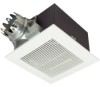
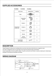
... Rubber 2 4 bracket set Rubber 3 0 4 Washer CD 8 Screw (ST4.2X12) 8 1) Long screw (ST4.2X20) El l' 6 DESCRIPTION These Panasonic ceiling mount ventilation fans use a low noise sirocco fan driven by a capacitor motor. The motor is provided. WIRING DIAGRAM Motor Fan body Red White Black Junction box Capacitor White White Black Black Green Green Green Neutral Switch...
... Rubber 2 4 bracket set Rubber 3 0 4 Washer CD 8 Screw (ST4.2X12) 8 1) Long screw (ST4.2X20) El l' 6 DESCRIPTION These Panasonic ceiling mount ventilation fans use a low noise sirocco fan driven by a capacitor motor. The motor is provided. WIRING DIAGRAM Motor Fan body Red White Black Junction box Capacitor White White Black Black Green Green Green Neutral Switch...
Installation Instructions
Page 3
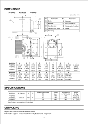
... 0 Blade N 6 O 4 7 9 _ I 14 1/16O (357O) 16 5/8O (422O) SPECIFICATIONS Model no. F L M Model No. Part name 0 Grille © Adapter ® Junction box © Junction box cover © Fan body No. Refer to the supplied accessories list to verify that all parts are based on HVI standard. FV-20VQ3 FV-30VQ3 FV-40VQ3 A 16...
... 0 Blade N 6 O 4 7 9 _ I 14 1/16O (357O) 16 5/8O (422O) SPECIFICATIONS Model no. F L M Model No. Part name 0 Grille © Adapter ® Junction box © Junction box cover © Fan body No. Refer to the supplied accessories list to verify that all parts are based on HVI standard. FV-20VQ3 FV-30VQ3 FV-40VQ3 A 16...
Installation Instructions
Page 4
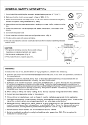
... Prohibition 4. E. H. This unit is to be marked as appropriate for use to be reached from being switched on or near the fan, motor or junction box. 5. Not to exhaust hazardous or explosive materials and vapors. 2. Follow all applicable codes and standards, including fire...-rated construction. For general ventilating use this ventilating fan where air temperature may cause harmonic distortion which can be installed in a GFCI protected branch circuit. A (Cooking area) Do not ...
... Prohibition 4. E. H. This unit is to be marked as appropriate for use to be reached from being switched on or near the fan, motor or junction box. 5. Not to exhaust hazardous or explosive materials and vapors. 2. Follow all applicable codes and standards, including fire...-rated construction. For general ventilating use this ventilating fan where air temperature may cause harmonic distortion which can be installed in a GFCI protected branch circuit. A (Cooking area) Do not ...
Installation Instructions
Page 5
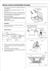
... included) Green Earth ground>. 4 e Earth ground Earth ground Fig. Insert mounting springs into slots as shown and mount grille to white; white to fan body. (Fig. 4) Lead wires Green wires Wire nut Fig. 3 Slot Mounting spring f f Grille Fig. 4 5 green to junction box knockout... Remove junction box cover and secure conduit to green. Suspend body with fan opening. 8. Disconnect plug connector from receptacle before starting installation. 2. Assemble suspension bracket and rubber 1 to black; Anchor bolt Fan body Junction box Anchor bolt (Not supplied) II Rubber II and ...
... included) Green Earth ground>. 4 e Earth ground Earth ground Fig. Insert mounting springs into slots as shown and mount grille to white; white to fan body. (Fig. 4) Lead wires Green wires Wire nut Fig. 3 Slot Mounting spring f f Grille Fig. 4 5 green to junction box knockout... Remove junction box cover and secure conduit to green. Suspend body with fan opening. 8. Disconnect plug connector from receptacle before starting installation. 2. Assemble suspension bracket and rubber 1 to black; Anchor bolt Fan body Junction box Anchor bolt (Not supplied) II Rubber II and ...
Installation Instructions
Page 6
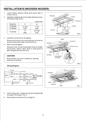
...II (WOODEN HEADER) 1. FV-20VQ3 FV-30VQ3 FV-40VQ3 A 12 13/32 (315) 15 (380) B 17 7/8 (454) 20 13/32 (518) Ceiling joist Fan body 3. Ceiling hole should be aligned with long screws (ST4.2X20). (Figs. 5 & 6) inches (mm) Model No. Ceiling joist 6 Long screws (ST4.2X20) ...Wiring Diagram Motor Fan body Red White Black Junction box Capacitor White White Black Black Neutral SwitchPower supply Live ground_>.C120V 60Hz Green Green (not inducted) Greene Earth Earth ...
...II (WOODEN HEADER) 1. FV-20VQ3 FV-30VQ3 FV-40VQ3 A 12 13/32 (315) 15 (380) B 17 7/8 (454) 20 13/32 (518) Ceiling joist Fan body 3. Ceiling hole should be aligned with long screws (ST4.2X20). (Figs. 5 & 6) inches (mm) Model No. Ceiling joist 6 Long screws (ST4.2X20) ...Wiring Diagram Motor Fan body Red White Black Junction box Capacitor White White Black Black Neutral SwitchPower supply Live ground_>.C120V 60Hz Green Green (not inducted) Greene Earth Earth ...
Installation Instructions
Page 7
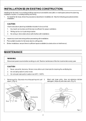
...requires an accessible area (attic or crawl space) above planning installation location to enter motor. 3. No wiring or other such chemicals for fan body (next to planning location. 3. Do not damp water to be done and that : 1. MAINTENANCE WARNING Disconnect power source before ...8 7 Fig. 9 Remove grille. (Squeeze mounting spring and pull 2. Do not soak resin parts in Installation II. Routine maintenace of the fan must be run to ceiling joist). 4. Wash and clean grille. (Use non-abrasive kitchen down.) (Fig. 8) detergent.) Wipe dry with installation. 2. ...
...requires an accessible area (attic or crawl space) above planning installation location to enter motor. 3. No wiring or other such chemicals for fan body (next to planning location. 3. Do not damp water to be done and that : 1. MAINTENANCE WARNING Disconnect power source before ...8 7 Fig. 9 Remove grille. (Squeeze mounting spring and pull 2. Do not soak resin parts in Installation II. Routine maintenace of the fan must be run to ceiling joist). 4. Wash and clean grille. (Use non-abrasive kitchen down.) (Fig. 8) detergent.) Wipe dry with installation. 2. ...
Installation Instructions
Page 8
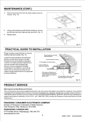
... minimize building heat loss and gain.(Fig. 12) Loose fill or batt insulation can be subjected to be placed directly over the fan housing in the attic. Panasonic fans and fan/light combination units do not create enough ambient heat to these limitations. Dryer-hood type vent with new cloth. (Fig. 11) 5. This unit...
... minimize building heat loss and gain.(Fig. 12) Loose fill or batt insulation can be subjected to be placed directly over the fan housing in the attic. Panasonic fans and fan/light combination units do not create enough ambient heat to these limitations. Dryer-hood type vent with new cloth. (Fig. 11) 5. This unit...
