
FV08VKL1 User Guide
Page 1
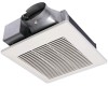
Failure to install, operate or service the Panasonic Ventilating Fan. Please read these instructions carefully before attempting to comply with instructions could result in personal injury and/or property damage. INSTALLATION INSTRUCTIONS Ventilating Fan FV-08VKL1 g N e Panasonid READ AND SAVE THESE INSTRUCTIONS. Please retain this booklet for future reference. Table of Contents Supplied Accessories...
Failure to install, operate or service the Panasonic Ventilating Fan. Please read these instructions carefully before attempting to comply with instructions could result in personal injury and/or property damage. INSTALLATION INSTRUCTIONS Ventilating Fan FV-08VKL1 g N e Panasonid READ AND SAVE THESE INSTRUCTIONS. Please retain this booklet for future reference. Table of Contents Supplied Accessories...
FV08VKL1 User Guide
Page 2
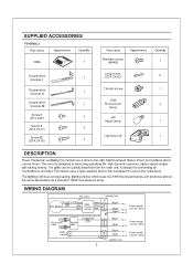
...lamp 1 -..ftftift, Lighting unit „ At:,/_r,,„ or !At, 1 DESCRIPTION These Panasonic ventilating fan models use a sirocco fan with saving eneray. The blower uses a high-capacity sirocco fan developed to have long operating life, high dynamic response, higher speed ranges with dolphin-shaped blades driven...lighting device which uses two 18W fluorescent lamps and produces almost the same illumination as a standard 100W incandescent lamp. WIRING DIAGRAM Fan body A7 , Thermal Cutoff Black C o ontrol 86°C Red Main Blue Circuit Junction box Black White Red / (3(...
...lamp 1 -..ftftift, Lighting unit „ At:,/_r,,„ or !At, 1 DESCRIPTION These Panasonic ventilating fan models use a sirocco fan with saving eneray. The blower uses a high-capacity sirocco fan developed to have long operating life, high dynamic response, higher speed ranges with dolphin-shaped blades driven...lighting device which uses two 18W fluorescent lamps and produces almost the same illumination as a standard 100W incandescent lamp. WIRING DIAGRAM Fan body A7 , Thermal Cutoff Black C o ontrol 86°C Red Main Blue Circuit Junction box Black White Red / (3(...
FV08VKL1 User Guide
Page 3
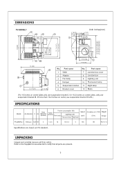
UNPACKING Unpack and carefully remove unit from carton. Part name 1 Grille 2 Adaptor 3 Fan body 4 Damper 5 Suspension bracket 6 Bracket cover No. Part name 7 Junction box cover 8 Junction box 9 Lighting unit 10 Fluorescent lamp 11 Night lamp 12 Blade (For ...
UNPACKING Unpack and carefully remove unit from carton. Part name 1 Grille 2 Adaptor 3 Fan body 4 Damper 5 Suspension bracket 6 Bracket cover No. Part name 7 Junction box cover 8 Junction box 9 Lighting unit 10 Fluorescent lamp 11 Night lamp 12 Blade (For ...

FV08VKL1 User Guide
Page 4
... disconnect the power source before working on accidentally. Provide suction parts with any questions, contact the manufacturer. Ducted fans must be installed in Fig. For disposal or recycling information, please contact your community due to prevent backdrafting. Do not use this...a value greater than R40. (This is approved for use only. B) 3. This product must always be reached from being switched on or near the fan, motor or light fixture. 5. Use this area CAUTION: 1. B. I. A Alliance: http://www.eiae.org (Cooking area) Do not install above ...
... disconnect the power source before working on accidentally. Provide suction parts with any questions, contact the manufacturer. Ducted fans must be installed in Fig. For disposal or recycling information, please contact your community due to prevent backdrafting. Do not use this...a value greater than R40. (This is approved for use only. B) 3. This product must always be reached from being switched on or near the fan, motor or light fixture. 5. Use this area CAUTION: 1. B. I. A Alliance: http://www.eiae.org (Cooking area) Do not install above ...
FV08VKL1 User Guide
Page 5
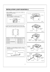
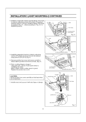
... I (ST4.2X8) Suspension bracketIII Suspension bracket II Suspension bracket M 0 " ,„ o Fan body Suspension bracket III Suspension bracket II "Cl t~Qll.ll 0 .. ,V Fan body j Suspension bracket I Fig. 2-3 a ° Suspension bracket I Fan body ode Suspension bracket M Fig. 2-2 If spacing A on center joists is 24 inches,... installation. bracket I Fig. 2-4 5 INSTALLATION I (JOIST MOUNTING-I Fig. 2-1 e ..:. Damper Tape Fan body 00- Insert the suspension bracket into the fan body and adaptor. (select the suspension bracket as shown below : Thumb screw Adaptor _ -
... I (ST4.2X8) Suspension bracketIII Suspension bracket II Suspension bracket M 0 " ,„ o Fan body Suspension bracket III Suspension bracket II "Cl t~Qll.ll 0 .. ,V Fan body j Suspension bracket I Fig. 2-3 a ° Suspension bracket I Fan body ode Suspension bracket M Fig. 2-2 If spacing A on center joists is 24 inches,... installation. bracket I Fig. 2-4 5 INSTALLATION I (JOIST MOUNTING-I Fig. 2-1 e ..:. Damper Tape Fan body 00- Insert the suspension bracket into the fan body and adaptor. (select the suspension bracket as shown below : Thumb screw Adaptor _ -
FV08VKL1 User Guide
Page 6
...relief to green; Install a duct and secure it to install the product) Joist Joist Fan body 2 Long screws (ST4.2X20) Fig. 3-1 Fan body 4. Refer to wiring diagram of fan body according to Fig. 3-1, others according to Fig. 3-2 to the fan body by using screw II (ST4.2X12) (Fig. 4) 5. INSTALLATION I (JOIST ... screws (ST4.2X20) ( If spacing A between joists is 12 inches, install the flange of page 2. Install the suspension bracket and the flange of fan body to joists by using long screws (ST4.2X20) and secure it with duct tape or clamps. 4 Long screws(ST4.2X20) Fig. 3-2 Joist...
...relief to green; Install a duct and secure it to install the product) Joist Joist Fan body 2 Long screws (ST4.2X20) Fig. 3-1 Fan body 4. Refer to wiring diagram of fan body according to Fig. 3-1, others according to Fig. 3-2 to the fan body by using screw II (ST4.2X12) (Fig. 4) 5. INSTALLATION I (JOIST ... screws (ST4.2X20) ( If spacing A between joists is 12 inches, install the flange of page 2. Install the suspension bracket and the flange of fan body to joists by using long screws (ST4.2X20) and secure it with duct tape or clamps. 4 Long screws(ST4.2X20) Fig. 3-2 Joist...
FV08VKL1 User Guide
Page 7
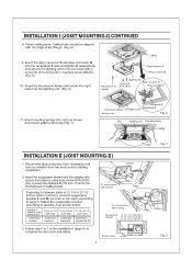
...) (336-394) suspension suspension bracket bracket I ) CONTINUED 8. Select the suspension bracket according to spacing A as shown and mount grille to fan body.(Fig. 7) Receptacle II Receptacle III Fluorescent lamps 4 W Night Lamp inches (mm) Fig. 6 Slot Lighting unit Mounting spring Ceiling Grille... II (JOIST MOUNTING-II) 1. Follow step 5 to complete the duct work . Disconnect plug connector from receptacle and remove adaptor from fan body before starting installation. 2. Insert the fluorescent lamps and screw the night lamp into slots as shown below. inches (mm) 7/8 ...
...) (336-394) suspension suspension bracket bracket I ) CONTINUED 8. Select the suspension bracket according to spacing A as shown and mount grille to fan body.(Fig. 7) Receptacle II Receptacle III Fluorescent lamps 4 W Night Lamp inches (mm) Fig. 6 Slot Lighting unit Mounting spring Ceiling Grille... II (JOIST MOUNTING-II) 1. Follow step 5 to complete the duct work . Disconnect plug connector from receptacle and remove adaptor from fan body before starting installation. 2. Insert the fluorescent lamps and screw the night lamp into slots as shown below. inches (mm) 7/8 ...

FV08VKL1 User Guide
Page 8
.... 11) 8. When mounting body and blower separately 3 Screws Adaptor 1. Loosen 3 screws (but do not remove them from fan body and secure it to fan body by using screw II(ST4.2X12) in Fig.8 of page 7. Secure the suspension bracket to joists by using long screws... into joists. (Fig. 9) IMPORTANT: Make sure that adaptor claws are properly inserted into the fan body. (Fig. 12-3) O Joist Fig. 12-3 8. Insert fan body (without Fan body 0 blower section) into fan body (refering to joists by using long screw (ST4.2X20) (Fig. 11) 7. INSTALLATION II ( JOIST MOUNTING-II ) ...
.... 11) 8. When mounting body and blower separately 3 Screws Adaptor 1. Loosen 3 screws (but do not remove them from fan body and secure it to fan body by using screw II(ST4.2X12) in Fig.8 of page 7. Secure the suspension bracket to joists by using long screws... into joists. (Fig. 9) IMPORTANT: Make sure that adaptor claws are properly inserted into the fan body. (Fig. 12-3) O Joist Fig. 12-3 8. Insert fan body (without Fan body 0 blower section) into fan body (refering to joists by using long screw (ST4.2X20) (Fig. 11) 7. INSTALLATION II ( JOIST MOUNTING-II ) ...
FV08VKL1 User Guide
Page 9
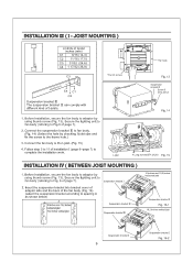
... to 11 of page 7). 2. Secure the lighting unit to fan body (refering to Fig.6 of installation I -joist. (Fig. 15) 4. Before installation, secure the fan body to fan body. (Fig. 14) (Select the hole by using thumb screw (Fig. 13). joist 0 Fan body c Fig. 13 Suspension bracket III Screw II (ST4....° . ' C4 C1 C2 Suspension bracket III The suspension bracket M can comply with different kind of page 7). Secure the lighting unit to fan body (refering to Fig. 6 of I -joist size and fix the screw to adaptor by using thumb screw (Fig. 13). Before installation, secure the...
... to 11 of page 7). 2. Secure the lighting unit to fan body (refering to Fig.6 of installation I -joist. (Fig. 15) 4. Before installation, secure the fan body to fan body. (Fig. 14) (Select the hole by using thumb screw (Fig. 13). joist 0 Fan body c Fig. 13 Suspension bracket III Screw II (ST4....° . ' C4 C1 C2 Suspension bracket III The suspension bracket M can comply with different kind of page 7). Secure the lighting unit to fan body (refering to Fig. 6 of I -joist size and fix the screw to adaptor by using thumb screw (Fig. 13). Before installation, secure the...

FV08VKL1 User Guide
Page 10
... installation work . 0 0 0 Joist Fig. 19 INSTALLATION V ( WOODEN HEADER ) 1. Follow step 5 to adaptor by using long screws(ST4.2X20) (Fig. 18, Fig. 19) Joists Fan body Junction box Adaptor 13 1/4-153/4 ( 336-400 ) A 16 1/2-183/4 (419-480) 3-5 ( 76-126 ) 5 4/5-7 4/5 ( 48-198) inches(mm) 7/8 (21.6) Fig...) with the joists.(Fig. 17) Keep the distance B (7/8 inch, 21.6mm) for the thickness of installation I (page 6-page 7) to fan body by using thumb screw (Fig. 13 of page 9). Install header between joists. Secure the suspension bracket to complete the installation work . 10...
... installation work . 0 0 0 Joist Fig. 19 INSTALLATION V ( WOODEN HEADER ) 1. Follow step 5 to adaptor by using long screws(ST4.2X20) (Fig. 18, Fig. 19) Joists Fan body Junction box Adaptor 13 1/4-153/4 ( 336-400 ) A 16 1/2-183/4 (419-480) 3-5 ( 76-126 ) 5 4/5-7 4/5 ( 48-198) inches(mm) 7/8 (21.6) Fig...) with the joists.(Fig. 17) Keep the distance B (7/8 inch, 21.6mm) for the thickness of installation I (page 6-page 7) to fan body by using thumb screw (Fig. 13 of page 9). Install header between joists. Secure the suspension bracket to complete the installation work . 10...
FV08VKL1 User Guide
Page 11
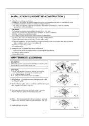
... Fig. 23 3. Wiring can be run to motor. 3. Routine maintenance must be sure that area is sufficient for cleaning the ventilating fan. 2. Slot Mounting spring CAUTION: 1. Remove grille. (Squeeze mounting spring and pull down carefully.) (Fig. 22) 2. Do not ... Before installation, provide inspection and maintenance access at a location that will not interfere with installation. (2) Remove ceiling section. (3) Install fan body. Installation from fan body using a vacuum cleaner.(Remove lamps if necessary.) (Fig. 24) 4. Installation in water over 60°C. 1. MAINTENANCE I...
... Fig. 23 3. Wiring can be run to motor. 3. Routine maintenance must be sure that area is sufficient for cleaning the ventilating fan. 2. Slot Mounting spring CAUTION: 1. Remove grille. (Squeeze mounting spring and pull down carefully.) (Fig. 22) 2. Do not ... Before installation, provide inspection and maintenance access at a location that will not interfere with installation. (2) Remove ceiling section. (3) Install fan body. Installation from fan body using a vacuum cleaner.(Remove lamps if necessary.) (Fig. 24) 4. Installation in water over 60°C. 1. MAINTENANCE I...
FV08VKL1 User Guide
Page 12
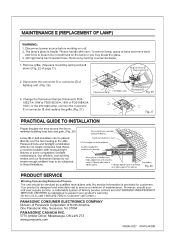
...To remove lamp, grasp at all flex joints. Remove by qualified technicians only. Panasonic fans and fan/light combination units do not create enough ambient heat to be placed directly over the fan housing in the attic. The lamp's glass is provided for customers. Change the...27 PRACTICAL GUIDE TO INSTALLATION Proper insulate the area around the fan to ensure a minimum of North America, One Panasonic Way, Secaucus, NJ 07094 PANASONIC CANADA INC. 5770 Ambler Driver, Mississauga, ON L4W 2T3 www.panasonic.com X0206-2027 08VKL4420B Fig. 28 PRODUCT SERVICE Warning Concerning ...
...To remove lamp, grasp at all flex joints. Remove by qualified technicians only. Panasonic fans and fan/light combination units do not create enough ambient heat to be placed directly over the fan housing in the attic. The lamp's glass is provided for customers. Change the...27 PRACTICAL GUIDE TO INSTALLATION Proper insulate the area around the fan to ensure a minimum of North America, One Panasonic Way, Secaucus, NJ 07094 PANASONIC CANADA INC. 5770 Ambler Driver, Mississauga, ON L4W 2T3 www.panasonic.com X0206-2027 08VKL4420B Fig. 28 PRODUCT SERVICE Warning Concerning ...
