
FV08VKL4 User Guide
Page 1
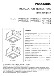
... Indication 7 Operation 7 Installation I ) 8-9 Installation II (Suspension Brackets Mounting) - - - - 10 Installation III (Joist Mounting - Failure to install, operate or service the Panasonic product. II) 10 Maintenance I (Cleaning) 11 MaintenanceII (Replacement of lamp) 11 Practical Guide To Installation Back cover Specifications Back cover Product Service Back cover READ AND SAVE THESE INSTRUCTIONS Thank you for purchasing this booklet for future reference. Please explain to users how to operate and...
... Indication 7 Operation 7 Installation I ) 8-9 Installation II (Suspension Brackets Mounting) - - - - 10 Installation III (Joist Mounting - Failure to install, operate or service the Panasonic product. II) 10 Maintenance I (Cleaning) 11 MaintenanceII (Replacement of lamp) 11 Practical Guide To Installation Back cover Specifications Back cover Product Service Back cover READ AND SAVE THESE INSTRUCTIONS Thank you for purchasing this booklet for future reference. Please explain to users how to operate and...
FV08VKL4 User Guide
Page 2
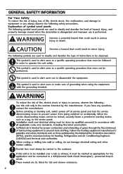
...models are used to alert users to make sure of grounding when using the equipment with all applicable codes and standards, including fire-rated construction. 0 Sufficient air is used to alert users to a specific operating procedure that must be vented to a GFCI(Ground Fault Circuit Interrupter) - O Before servicing or cleaning unit, switch power off at service...observe the following symbols are used to classify and describe the type of fuel burning equipment to prevent power from being switched on accidentally. O Installation work and electrical wiring must be locked, ...
...models are used to alert users to make sure of grounding when using the equipment with all applicable codes and standards, including fire-rated construction. 0 Sufficient air is used to alert users to a specific operating procedure that must be vented to a GFCI(Ground Fault Circuit Interrupter) - O Before servicing or cleaning unit, switch power off at service...observe the following symbols are used to classify and describe the type of fuel burning equipment to prevent power from being switched on accidentally. O Installation work and electrical wiring must be locked, ...
FV08VKL4 User Guide
Page 3
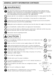
... is to no longer be used, it from sharp edges, oil, grease, hot surfaces, chemicals or other objects. Fig. Cooking equipment Fig. ACAUTION Do not install this fan with any solid-state speed control device. GENERAL SAFETY INFORMATION CONTINUED A WARNING A USA only: This product has two fluorescent lamps that the electric service supply voltage is AC...
... is to no longer be used, it from sharp edges, oil, grease, hot surfaces, chemicals or other objects. Fig. Cooking equipment Fig. ACAUTION Do not install this fan with any solid-state speed control device. GENERAL SAFETY INFORMATION CONTINUED A WARNING A USA only: This product has two fluorescent lamps that the electric service supply voltage is AC...
FV08VKL4 User Guide
Page 4
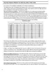
... PLEASE READ PRIOR TO INSTALLING THIS FAN [For models of: FV-13VKML4, FV...Control (Lower Setting). A High / Low Delay Timer, located inside the fan unit, is dependent on the amount of resistance. The installer no longer has to perform as rated, whether facing 0.1,0.2 or even 0.25 inches water...installer pre-set lower level (FV-13VKML4 and FV-13VKSL4:0,50,70,90, 110 CFM ; The bottom line is turned on the timer (0.5 - 60 minutes) and make the adjustments during the installation. These features need to be built using DC motor technology. By utilizing CustomVent Variable Speed Control...
... PLEASE READ PRIOR TO INSTALLING THIS FAN [For models of: FV-13VKML4, FV...Control (Lower Setting). A High / Low Delay Timer, located inside the fan unit, is dependent on the amount of resistance. The installer no longer has to perform as rated, whether facing 0.1,0.2 or even 0.25 inches water...installer pre-set lower level (FV-13VKML4 and FV-13VKSL4:0,50,70,90, 110 CFM ; The bottom line is turned on the timer (0.5 - 60 minutes) and make the adjustments during the installation. These features need to be built using DC motor technology. By utilizing CustomVent Variable Speed Control...
FV08VKL4 User Guide
Page 5
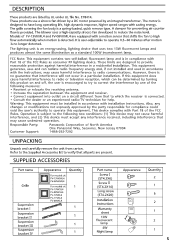
... turning this equipment. A damper for compliance could void the user's authority to operate this product on a circuit different from carton. The lighting unit is detected. Responsible Party: Panasonic Corporation of the FCC Rules as a standard 100W incandescent lamp. Refer to the Supplied Accessories list to verify that all parts are equipped with installation instructions. It is user-adjustable to operate...
... turning this equipment. A damper for compliance could void the user's authority to operate this product on a circuit different from carton. The lighting unit is detected. Responsible Party: Panasonic Corporation of the FCC Rules as a standard 100W incandescent lamp. Refer to the Supplied Accessories list to verify that all parts are equipped with installation instructions. It is user-adjustable to operate...
FV08VKL4 User Guide
Page 6
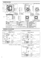
... box - - Live Neutral Live (Power supply) > (LIGHT) AC120V 60Hz AC120V 60Hz > (N.LIGHT) FV-13VKSL4 FV-08VKSL4 Fan body Wiring diagram Junction box DC-Motor Adjustment switch Green Fluorescent lamp (Self-ballasted) Night lamp Black White Red Red Green E)l Black White Black Live supply) Neutral •(VENT... L4 FV-1 3VKM L4 F No. 10 1/4 (260) 3 7/8 (100 Part name 3 7/8 (100).. Switdi box Earth ground Switch box -=j Live Neutral Live (Power supply) > (LIGHT) AC120V 60Hz • AC120V 60Hz >(N.LIGHT) FV-13VKL4 FV-11VKL4 FV-08VKL4 r Fan body DC-Motor Wiring diagram Junction ...
... box - - Live Neutral Live (Power supply) > (LIGHT) AC120V 60Hz AC120V 60Hz > (N.LIGHT) FV-13VKSL4 FV-08VKSL4 Fan body Wiring diagram Junction box DC-Motor Adjustment switch Green Fluorescent lamp (Self-ballasted) Night lamp Black White Red Red Green E)l Black White Black Live supply) Neutral •(VENT... L4 FV-1 3VKM L4 F No. 10 1/4 (260) 3 7/8 (100 Part name 3 7/8 (100).. Switdi box Earth ground Switch box -=j Live Neutral Live (Power supply) > (LIGHT) AC120V 60Hz • AC120V 60Hz >(N.LIGHT) FV-13VKL4 FV-11VKL4 FV-08VKL4 r Fan body DC-Motor Wiring diagram Junction ...
FV08VKL4 User Guide
Page 7
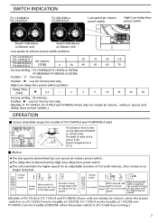
...1 2 3 5 10 20 30 60 Factory setting : 20 minutes. the delay time has passed. (Models of 0.5 to 10 feet (3m). Fan active At low speed When motion is 90°. j/ o ...-- When manual wall When manual wall switch is opened, At low switch is ...stop running.) 7 O 90° (Room temperature is 25 °C) • Motion • The low speed is determined by Low speed air volume preset switch. • The delay time is no longer detected. Remains running speed fan runs at the high at the high speed. Position : use for factory test only. (Models...
...1 2 3 5 10 20 30 60 Factory setting : 20 minutes. the delay time has passed. (Models of 0.5 to 10 feet (3m). Fan active At low speed When motion is 90°. j/ o ...-- When manual wall When manual wall switch is opened, At low switch is ...stop running.) 7 O 90° (Room temperature is 25 °C) • Motion • The low speed is determined by Low speed air volume preset switch. • The delay time is no longer detected. Remains running speed fan runs at the high at the high speed. Position : use for factory test only. (Models...
FV08VKL4 User Guide
Page 8
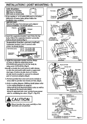
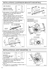
...(Wiring detail please refer to the wiring diagram on page 6) Follow all the local electrical safety codes as well as shown below ) (Fig.1) Suspension bracket connect method: Suspension bracket I as the National Electrical Code (NEC). Using UL approved wire nuts, connect house power wires to junction box knock-out hole. (...v% Suspension WI- If the spacing A is needed to connect to relevant part of frame to joists by using long screws (ST4.2X20) and secure it to the fan body by using screw II (ST4.2X14). (Fig.2) 4.Install a circular duct and secure it with clamps, or wire ties and seal...
...(Wiring detail please refer to the wiring diagram on page 6) Follow all the local electrical safety codes as well as shown below ) (Fig.1) Suspension bracket connect method: Suspension bracket I as the National Electrical Code (NEC). Using UL approved wire nuts, connect house power wires to junction box knock-out hole. (...v% Suspension WI- If the spacing A is needed to connect to relevant part of frame to joists by using long screws (ST4.2X20) and secure it to the fan body by using screw II (ST4.2X14). (Fig.2) 4.Install a circular duct and secure it with clamps, or wire ties and seal...
FV08VKL4 User Guide
Page 9
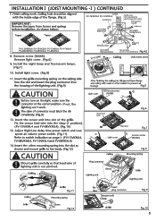
...lighting can't work . O The claw of lighting unit is not pinched. Finish ceiling work . Fix the sensor lead wire into slot of the flange. (Fig.5) MPORTANT: Remove the tapes from louver and springs before installation. Adjust High/Low delay time preset switch and Low speed air volume preset switch. (Fig.11) Refer to manual... reducing the electromagnetic noise) Earth ground to green Wire nut Live to prevent air leakage Fig.5 ACAUTION Light cover ® Remove screw (M4X8) O Before turn on the wiring side into the slot and insert the plug connector into the slot as shown and ...
...lighting can't work . O The claw of lighting unit is not pinched. Finish ceiling work . Fix the sensor lead wire into slot of the flange. (Fig.5) MPORTANT: Remove the tapes from louver and springs before installation. Adjust High/Low delay time preset switch and Low speed air volume preset switch. (Fig.11) Refer to manual... reducing the electromagnetic noise) Earth ground to green Wire nut Live to prevent air leakage Fig.5 ACAUTION Light cover ® Remove screw (M4X8) O Before turn on the wiring side into the slot and insert the plug connector into the slot as shown and ...
FV08VKL4 User Guide
Page 10
... connect method: Suspension bracket I and II connect with screw I as shown below . 2. Install the suspension bracket to joists by using long screws (ST4.2X20)(Fig.14) and secure it to the fan body by using screw II (ST4.2X14). (Fig.15) 4. Joist O Fan body 6 Long screws (...I Fig.13 Unit: inches (mm) Suspension bracket II -----.....4, , Suspension %A. 4_ Screw I (ST4.2X6) bracket I 3. Follow steps 4 to 14 of installation I (page 8, page 9 ) to complete the installation work . Follow steps 4 to 14 of frame. (Fig. 16) 3. B ir 1fr . If the spacing B is 10 1/2 inches (266 mm) to ...
... connect method: Suspension bracket I and II connect with screw I as shown below . 2. Install the suspension bracket to joists by using long screws (ST4.2X20)(Fig.14) and secure it to the fan body by using screw II (ST4.2X14). (Fig.15) 4. Joist O Fan body 6 Long screws (...I Fig.13 Unit: inches (mm) Suspension bracket II -----.....4, , Suspension %A. 4_ Screw I (ST4.2X6) bracket I 3. Follow steps 4 to 14 of installation I (page 8, page 9 ) to complete the installation work . Follow steps 4 to 14 of frame. (Fig. 16) 3. B ir 1fr . If the spacing B is 10 1/2 inches (266 mm) to ...
FV08VKL4 User Guide
Page 11
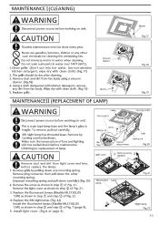
... source before working on unit. Install light cover. (Fig.8 of lens and lighting unit has cooled down one mounting spring. Wipe dry with clean cloth) (Fig.17) 2. Remove grille by turning counterclockwise. Replace the fluorescent lamps (Maxlite MLS13GU35 13W) as shown in water over 140°F (60°C). 1.Clean grille. (Don't put into hot water. To remove, pull out carefully. Replace the 4W...
... source before working on unit. Install light cover. (Fig.8 of lens and lighting unit has cooled down one mounting spring. Wipe dry with clean cloth) (Fig.17) 2. Remove grille by turning counterclockwise. Replace the fluorescent lamps (Maxlite MLS13GU35 13W) as shown in water over 140°F (60°C). 1.Clean grille. (Don't put into hot water. To remove, pull out carefully. Replace the 4W...
FV08VKL4 User Guide
Page 12
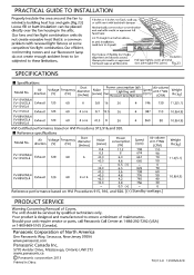
... Air direction Voltage (V) Frequency (Hz) diameter (inches) Noise (sones) Fan Lighting unit Fluorescent lamp Night lamp S(rppemed) at all flex joints Insulation Foil tape tightly covers all metal duct joints (glue PVC joints) Fig.23 SPECIFICATIONS • Specifications Model No. PRACTICAL GUIDE TO INSTALLATION Properly insulate... motors and our fluorescent lamp do not create excessive heat that is a common problem with mastic or approved foil faced tape 2-3 ft straight run before elbow In attic installation, caulk box to be placed directly over the fan housing in the attic.
... Air direction Voltage (V) Frequency (Hz) diameter (inches) Noise (sones) Fan Lighting unit Fluorescent lamp Night lamp S(rppemed) at all flex joints Insulation Foil tape tightly covers all metal duct joints (glue PVC joints) Fig.23 SPECIFICATIONS • Specifications Model No. PRACTICAL GUIDE TO INSTALLATION Properly insulate... motors and our fluorescent lamp do not create excessive heat that is a common problem with mastic or approved foil faced tape 2-3 ft straight run before elbow In attic installation, caulk box to be placed directly over the fan housing in the attic.

