
Installation Instructions
Page 1
... could result in personal injury and/or property damage. Failure to Installation Product Service 2 2 3 4 4 4-5 5 6-8 8-9 10 10-11 12 12 13 14 14 INSTALLATION INSTRUCTIONS Ventilating Fan FV-05VF2 FV-08VF2 FV-11VF2 Panasonid READ AND SAVE THESE INSTRUCTIONS. Please read these instructions carefully before attempting to install, operate or service the...
... could result in personal injury and/or property damage. Failure to Installation Product Service 2 2 3 4 4 4-5 5 6-8 8-9 10 10-11 12 12 13 14 14 INSTALLATION INSTRUCTIONS Ventilating Fan FV-05VF2 FV-08VF2 FV-11VF2 Panasonid READ AND SAVE THESE INSTRUCTIONS. Please read these instructions carefully before attempting to install, operate or service the...

Installation Instructions
Page 2
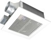
... (1P 1 Screw I (ST4.2X8) €) ) 2 Screw II (ST4.2X10) CC17 2 Suspension bracket I o 1 Suspension bracket II 1 Suspension bracket III 1 3 inches adaptor connector 1 (optional part) DESCRIPTION These Panasonic ventilation fans models use a sirocco fan with reduced energy consumption. The grille covering the...
... (1P 1 Screw I (ST4.2X8) €) ) 2 Screw II (ST4.2X10) CC17 2 Suspension bracket I o 1 Suspension bracket II 1 Suspension bracket III 1 3 inches adaptor connector 1 (optional part) DESCRIPTION These Panasonic ventilation fans models use a sirocco fan with reduced energy consumption. The grille covering the...

Installation Instructions
Page 3
Part name 1 Grille 2 Orifice cover 3 Junction box cover 4 Adaptor 5 Adaptor connector 6 Orifice 7 Blade No. Part name 8 Motor 9 Suspension bracket 10 Junction box 11 Damper 12 Fan body 13 Bracket cover (For 16 inches on center joists, only use suspension bracket I, for 19.2 inches on center joists, only use suspension bracket III, ...
Part name 1 Grille 2 Orifice cover 3 Junction box cover 4 Adaptor 5 Adaptor connector 6 Orifice 7 Blade No. Part name 8 Motor 9 Suspension bracket 10 Junction box 11 Damper 12 Fan body 13 Bracket cover (For 16 inches on center joists, only use suspension bracket I, for 19.2 inches on center joists, only use suspension bracket III, ...
Installation Instructions
Page 4
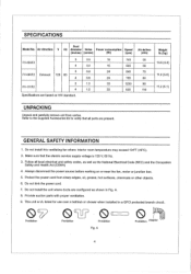
... Electrical Code (NEC) and the Occupation Safety and Health Act (OSHA) 4. Provide suction parts with proper ventilation. 9. A 0 Prohibition Adaptor 4 Do not install this ventilating fan where interior room temperature may exceed 104°F (40°C). 2. Follow all parts are present. Protect the power cord from carton. Make sure that all... Hz diameter Noise Power consumption Speed (inches) (sones) (W) (rpm) FV-05VF2 3 0.5 4 0.4 3 0.8 FV-08VF2 Exhaust 120 60 4 0.8 FV-11VF2 3 1.5 4 1.5 Specifications are based on or near the fan, motor or junction box. 5.
... Electrical Code (NEC) and the Occupation Safety and Health Act (OSHA) 4. Provide suction parts with proper ventilation. 9. A 0 Prohibition Adaptor 4 Do not install this ventilating fan where interior room temperature may exceed 104°F (40°C). 2. Follow all parts are present. Protect the power cord from carton. Make sure that all... Hz diameter Noise Power consumption Speed (inches) (sones) (W) (rpm) FV-05VF2 3 0.5 4 0.4 3 0.8 FV-08VF2 Exhaust 120 60 4 0.8 FV-11VF2 3 1.5 4 1.5 Specifications are based on or near the fan, motor or junction box. 5.

Installation Instructions
Page 5
...\\// 1 Do not install above or inside this unit only in the manner intended by qualified person(s) in Canada only.) WIRING DIAGRAM Fan body Motor Red White Junction box 1T Capacitor White - C. When,cutting or drilling into wall or ceiling, do not damage electrical ...Refrigeration and Air Conditioning Engineers (ASHRAE) and the local code authorities. Sufficient air is required for tub and shower enclosures. Ducted fans must be reached from being switched on accidentally. For general ventilating use only. Follow the heating equipment manufacturer's guideline and safety ...
...\\// 1 Do not install above or inside this unit only in the manner intended by qualified person(s) in Canada only.) WIRING DIAGRAM Fan body Motor Red White Junction box 1T Capacitor White - C. When,cutting or drilling into wall or ceiling, do not damage electrical ...Refrigeration and Air Conditioning Engineers (ASHRAE) and the local code authorities. Sufficient air is required for tub and shower enclosures. Ducted fans must be reached from being switched on accidentally. For general ventilating use only. Follow the heating equipment manufacturer's guideline and safety ...
Installation Instructions
Page 6
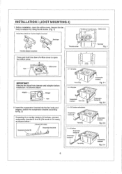
.... INSTALLATION I (JOIST MOUNTING-I (ST4.2X8) Suspension bracket III Suspension bracket II - . Insert the suspension bracket into the fan body and adaptor. (select the suspension bracket according to Fig. 2) If spacing A on center joists is 24 inches, connect...shown below : Adaptor . = I Fig. 2-3 A = 24 inches Suspension bracket DI Suspension () bracket II • Fan body .. . - - V 1 ... C) '. Fan body Suspension bracket I Fig. 2-4 6 Suspension bracket I Fig. 2-1 A= 16 inches • . . l Suspension - A = 19.2 inches vertical joists Suspension...
.... INSTALLATION I (JOIST MOUNTING-I (ST4.2X8) Suspension bracket III Suspension bracket II - . Insert the suspension bracket into the fan body and adaptor. (select the suspension bracket according to Fig. 2) If spacing A on center joists is 24 inches, connect...shown below : Adaptor . = I Fig. 2-3 A = 24 inches Suspension bracket DI Suspension () bracket II • Fan body .. . - - V 1 ... C) '. Fan body Suspension bracket I Fig. 2-4 6 Suspension bracket I Fig. 2-1 A= 16 inches • . . l Suspension - A = 19.2 inches vertical joists Suspension...
Installation Instructions
Page 7
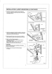
Fan body 2 Long screws > (ST4.2X20) Fig. 3-2 Joist 2 Long screws (ST4.2X20) O CD 0 Screw D(ST4.2X10) Fig. 4 Conduit ...a duct and secure it to black; green to white; Install the suspension bracket and the flange of fan body to joists by using long screws (ST4.2X20) according to Fig. 3, , Others Joist CD Fan body 4 Long screws (ST4.2X20) Fig. 3-1 A = 10 1/4-12 inches Joist 4. Install the... wires Green wires 7 Fig. 5 white to green; Using wire nuts, connect house power wires to ventilating fan wires: black to the fan body by using screw II (ST4.2X10) (Fig. 4) 5.
Fan body 2 Long screws > (ST4.2X20) Fig. 3-2 Joist 2 Long screws (ST4.2X20) O CD 0 Screw D(ST4.2X10) Fig. 4 Conduit ...a duct and secure it to black; green to white; Install the suspension bracket and the flange of fan body to joists by using long screws (ST4.2X20) according to Fig. 3, , Others Joist CD Fan body 4 Long screws (ST4.2X20) Fig. 3-1 A = 10 1/4-12 inches Joist 4. Install the... wires Green wires 7 Fig. 5 white to green; Using wire nuts, connect house power wires to ventilating fan wires: black to the fan body by using screw II (ST4.2X10) (Fig. 4) 5.
Installation Instructions
Page 8
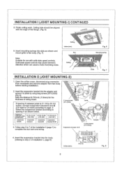
... ceiling work and wiring. 4. Solid-state speed controls may cause harmonic distortion which can cause a motor humming noise. Insert the suspension bracket into fan body (refering to joists by using long screws (ST4.2X20) (Fig. 8) Keep the distance B (7/8 inch, 21.6mm) for use with... the edge of the Installation I (page 7) to fan body. (Fig. 7) 7 Ceiling inches (mm) Slot (irk \ \ Fig. 6 Mounting spring Note: Suitable for the thickness of Installation I, page 6) 2 Long screws \...
... ceiling work and wiring. 4. Solid-state speed controls may cause harmonic distortion which can cause a motor humming noise. Insert the suspension bracket into fan body (refering to joists by using long screws (ST4.2X20) (Fig. 8) Keep the distance B (7/8 inch, 21.6mm) for use with... the edge of the Installation I (page 7) to fan body. (Fig. 7) 7 Ceiling inches (mm) Slot (irk \ \ Fig. 6 Mounting spring Note: Suitable for the thickness of Installation I, page 6) 2 Long screws \...
Installation Instructions
Page 9
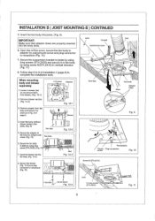
... (Fig. 11) 7. Secure the adaptor to joists as in vertical direction (Fig. 11) 8. INSTALLATION II ( JOIST MOUNTING-II ) CONTINUED 5, Insert the fan body into joists, (Fig. 9) IMPORTANT: Make sure that adaptor claws are properly inserted into joists. (Fig. 9) 5. Remove adaptor from blower). (Fig. 12.... (Fig. 12-3) 8. Secure the suspension bracket to joists by using long screws (ST4.2X20) and secure it to fan body by using thumb screw. (Fig. 10) 0 Fan body Fan body 0 Fig. 12-2 6. Remove blower section. (Fig. 12-2) 3. Follow step 8 to 9 of page 8. 4 Screws Adaptor O O 0 0 e...
... (Fig. 11) 7. Secure the adaptor to joists as in vertical direction (Fig. 11) 8. INSTALLATION II ( JOIST MOUNTING-II ) CONTINUED 5, Insert the fan body into joists, (Fig. 9) IMPORTANT: Make sure that adaptor claws are properly inserted into joists. (Fig. 9) 5. Remove adaptor from blower). (Fig. 12.... (Fig. 12-3) 8. Secure the suspension bracket to joists by using long screws (ST4.2X20) and secure it to fan body by using thumb screw. (Fig. 10) 0 Fan body Fan body 0 Fig. 12-2 6. Remove blower section. (Fig. 12-2) 3. Follow step 8 to 9 of page 8. 4 Screws Adaptor O O 0 0 e...

Installation Instructions
Page 10
...bracket M OM ill ft . Before installation, open the orifice cover. Connect the suspension bracket DI to fan body. (Fig. 13) (Select the hole by using thumb screw. (Fig.1 of the fan body. (Fig.15) (select the suspension bracket according to adaptor by using thumb screw. (Fig. 1...ts, • . Before installation, open the orifice cover. Secure the fan body to spacing A as shown below) A A___ /L._ 16 Inches and 19,2 f inches horizontal joist e.-. Connect the fan body to the frame hole.) 3. Secure the fan body to adaptor by checking Hoist size fix the screw to the I-...
...bracket M OM ill ft . Before installation, open the orifice cover. Connect the suspension bracket DI to fan body. (Fig. 13) (Select the hole by using thumb screw. (Fig.1 of the fan body. (Fig.15) (select the suspension bracket according to adaptor by using thumb screw. (Fig. 1...ts, • . Before installation, open the orifice cover. Secure the fan body to spacing A as shown below) A A___ /L._ 16 Inches and 19,2 f inches horizontal joist e.-. Connect the fan body to the frame hole.) 3. Secure the fan body to adaptor by checking Hoist size fix the screw to the I-...
Installation Instructions
Page 11
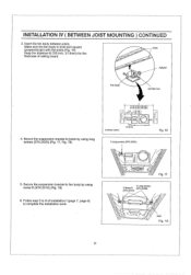
...to complete the installation work. 11 Fig. 17 4 Long screws 2 Screw II (ST4.2X20) (ST4.2X10) Joist Fig. 18 Make sure the fan body is level and square Joists (perpendicular) with the joists.(Fig. 16) Keep the distance B (7/8 inch, 21.6mm) for the thickness of ...installation I (page 7, page 8) to fan body by using screw II (ST4.2X10) (Fig. 18) 6. INSTALLATION IV ( BETWEEN JOIST MOUNTING ) CONTINUED 3, Insert the fan body between joists. j Fan body Adaptor Junction box 4. Follow step 5 to 9 of ceiling board.
...to complete the installation work. 11 Fig. 17 4 Long screws 2 Screw II (ST4.2X20) (ST4.2X10) Joist Fig. 18 Make sure the fan body is level and square Joists (perpendicular) with the joists.(Fig. 16) Keep the distance B (7/8 inch, 21.6mm) for the thickness of ...installation I (page 7, page 8) to fan body by using screw II (ST4.2X10) (Fig. 18) 6. INSTALLATION IV ( BETWEEN JOIST MOUNTING ) CONTINUED 3, Insert the fan body between joists. j Fan body Adaptor Junction box 4. Follow step 5 to 9 of ceiling board.
Installation Instructions
Page 12
... location that : 1. No wiring or other obstructions shall interfere with installation. (3) Plan suitable location for proper ventilation. 2. Secure the fan body to planning location. 3. Wiring can be run to adaptor by using long screws (ST4.2X20) (Fig. 19, Fig. 20...and wiring before installation. Installation from accessible area above the planning installation location or existing ducting and wiring. (1) To install the ventilating fan, follow the procedures described in installation II. (5) First, remove ceiling section according to Fig. 6 of Joist page 6) 2. ...
... location that : 1. No wiring or other obstructions shall interfere with installation. (3) Plan suitable location for proper ventilation. 2. Secure the fan body to planning location. 3. Wiring can be run to adaptor by using long screws (ST4.2X20) (Fig. 19, Fig. 20...and wiring before installation. Installation from accessible area above the planning installation location or existing ducting and wiring. (1) To install the ventilating fan, follow the procedures described in installation II. (5) First, remove ceiling section according to Fig. 6 of Joist page 6) 2. ...
Installation Instructions
Page 13
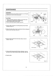
CAUTION: 1, Never use petrol, benzene, thinner or any dirt from fan body using a vacuum cleaner. (Fig. 23) Fig. 22 Vacuum cleaner 4. Do not damp water to enter motor. 3. Replace grille. 0 13 Fig. 23 Fig. 24 MAINTENANCE ...) 2, Wash and clean grille. (Use non-abrasive kitchen detergent, wipe dry with kitchen detergent, remove any other such chemicals for cleaning the ventilating fan. 2. Remove dust and dirt from fan body. Gloves Grille 1. Using a cloth dampened with new cloth.) (Fig, 22) Slot Mounting spring Fig, 21 Grille 3. Wipe dry with new cloth...
CAUTION: 1, Never use petrol, benzene, thinner or any dirt from fan body using a vacuum cleaner. (Fig. 23) Fig. 22 Vacuum cleaner 4. Do not damp water to enter motor. 3. Replace grille. 0 13 Fig. 23 Fig. 24 MAINTENANCE ...) 2, Wash and clean grille. (Use non-abrasive kitchen detergent, wipe dry with kitchen detergent, remove any other such chemicals for cleaning the ventilating fan. 2. Remove dust and dirt from fan body. Gloves Grille 1. Using a cloth dampened with new cloth.) (Fig, 22) Slot Mounting spring Fig, 21 Grille 3. Wipe dry with new cloth...
Installation Instructions
Page 14
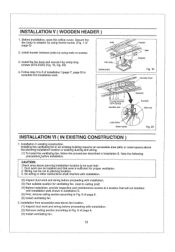
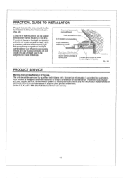
... duct helps alignment and absorbs Insulation. Dryer-hood type vent with recessed light fixtures or some competitors' fan/light combinations. PRACTICAL GUIDE TO INSTALLATION Properly insulate the area around the fan to these limitations. Panasonic fans and fan/light combination units do not create enough ambient heat to be subjected to minimize building heat loss...-292-7292 to ensure a minimum of factory service centers and AUTHORIZED INDEPENDENT SERVICE CENTERS is provided for customers. However, should be placed directly over the fan housing in the attic.
... duct helps alignment and absorbs Insulation. Dryer-hood type vent with recessed light fixtures or some competitors' fan/light combinations. PRACTICAL GUIDE TO INSTALLATION Properly insulate the area around the fan to these limitations. Panasonic fans and fan/light combination units do not create enough ambient heat to be subjected to minimize building heat loss...-292-7292 to ensure a minimum of factory service centers and AUTHORIZED INDEPENDENT SERVICE CENTERS is provided for customers. However, should be placed directly over the fan housing in the attic.
