
FV-07VFH3 Owner's Manual (English)
Page 1
Failure to install,operate or service the Panasonic product. Please retain this booklet for purchasing this booklet should be presented to Installation Specifications Product Service 2 2-4 5 5 5 6 6 7-11 12 ... could result in personal injury or property damage. FV-07VFH3 Contents General Safety Information Important Instructions Description Unpacking Supplied Accessories Dimensions Wiring Diagram Installation Operating instructions Maintenance Practical Guide to users. Please explain to users how to operate and maintain the product after installation, and this Panasonic product.
Failure to install,operate or service the Panasonic product. Please retain this booklet for purchasing this booklet should be presented to Installation Specifications Product Service 2 2-4 5 5 5 6 6 7-11 12 ... could result in personal injury or property damage. FV-07VFH3 Contents General Safety Information Important Instructions Description Unpacking Supplied Accessories Dimensions Wiring Diagram Installation Operating instructions Maintenance Practical Guide to users. Please explain to users how to operate and maintain the product after installation, and this Panasonic product.
FV-07VFH3 Owner's Manual (English)
Page 2
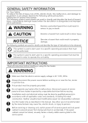
... service panel and have heater inspected by the manufacturer may cause fire, electric shock, or injury to persons. Use this manual. Installation work and electrical wiring must not be done by qualified person(s) in minor injury. Any other use is disregarded and improper use not recommended by a reputable electrician before reusing...
... service panel and have heater inspected by the manufacturer may cause fire, electric shock, or injury to persons. Use this manual. Installation work and electrical wiring must not be done by qualified person(s) in minor injury. Any other use is disregarded and improper use not recommended by a reputable electrician before reusing...
FV-07VFH3 Owner's Manual (English)
Page 3
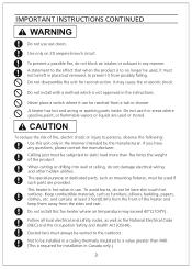
... any questions, please contact the manufacturer. Do not use it can be used, it from a tub or shower. To avoid burns, do not damage electrical wiring and other hidden utilities. Do not install this unit only in the manner intended by the manufacturer. Celiling joist must always be vented to no...
... any questions, please contact the manufacturer. Do not use it can be used, it from a tub or shower. To avoid burns, do not damage electrical wiring and other hidden utilities. Do not install this unit only in the manner intended by the manufacturer. Celiling joist must always be vented to no...
FV-07VFH3 Owner's Manual (English)
Page 6
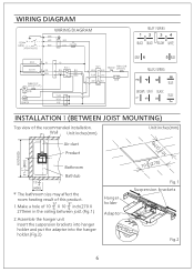
...) 2 3" 5 Air duct Product Bathroom Bathtub 17 3" 4 (450) The bathroom size may affect the room heating result of this product. 3" 3" 1.Make a hole of the recommended installation. WIRING DIAGRAM INSTALLATIONⅠ(BETWEEN JOIST MOUNTING) Top view of 10 X 10 inch(270 X 5 5 270mm in the ceiling between joist.(Fig.1) 2.Assemble the hanger unit Insert...
...) 2 3" 5 Air duct Product Bathroom Bathtub 17 3" 4 (450) The bathroom size may affect the room heating result of this product. 3" 3" 1.Make a hole of the recommended installation. WIRING DIAGRAM INSTALLATIONⅠ(BETWEEN JOIST MOUNTING) Top view of 10 X 10 inch(270 X 5 5 270mm in the ceiling between joist.(Fig.1) 2.Assemble the hanger unit Insert...

FV-07VFH3 Owner's Manual (English)
Page 7
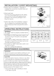
...2X30 tapping screws provided in the accessory package to fix the hanger unit to the ceiling.(Fig.3) (2) Using 4 of power wire and control lead wire. Slip the circular duct onto the adaptor and secure it with the national and local electrical codes having jurisdiction. 2.This ...the cord cover and stress relief two knockout holes.(Fig.5) ② Secure conduits, pass house power wires and control lead wires througth the holes. (Fig.6) Conduit Power wires (3 wires) Fig.5 Control lead wires(4 wires) Fig.6 7 The connection of the ST4.2X30 tapping screws provided in the accessory package to fix...
...2X30 tapping screws provided in the accessory package to fix the hanger unit to the ceiling.(Fig.3) (2) Using 4 of power wire and control lead wire. Slip the circular duct onto the adaptor and secure it with the national and local electrical codes having jurisdiction. 2.This ...the cord cover and stress relief two knockout holes.(Fig.5) ② Secure conduits, pass house power wires and control lead wires througth the holes. (Fig.6) Conduit Power wires (3 wires) Fig.5 Control lead wires(4 wires) Fig.6 7 The connection of the ST4.2X30 tapping screws provided in the accessory package to fix...
FV-07VFH3 Owner's Manual (English)
Page 8
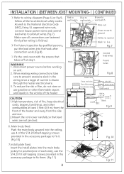
...-tapping screws provided in the accessory package to prevent excessive slack in the accessory package to product wires.(Fig.7) Make sure all the local electrical safety codes. When making wiring connections take care to fix it. (Fig.10) 7.Install plate fixed. Main body fixed.... INSTALLATIONⅠ(BETWEEN JOIST MOUNTING-Ⅰ) CONTINUED ③ Refer to live Fig.7 Control lead wines Power wires Green wire From red wire From blue wire From brown wire Fig.8 ON/OFF HEAT/VENT (wall switch) Green White N L Black E Fig.9 6. To reduce the risk of fire,...
...-tapping screws provided in the accessory package to prevent excessive slack in the accessory package to product wires.(Fig.7) Make sure all the local electrical safety codes. When making wiring connections take care to fix it. (Fig.10) 7.Install plate fixed. Main body fixed.... INSTALLATIONⅠ(BETWEEN JOIST MOUNTING-Ⅰ) CONTINUED ③ Refer to live Fig.7 Control lead wines Power wires Green wire From red wire From blue wire From brown wire Fig.8 ON/OFF HEAT/VENT (wall switch) Green White N L Black E Fig.9 6. To reduce the risk of fire,...
FV-07VFH3 Owner's Manual (English)
Page 11
...) to complete the install plate fixed,install plate locked,louve fixed and paste the switch labels. Heat On Fig.27 CAUTION: 1.Never use 4 of power wires and control lead wires. 6.Main body fixed.
...) to complete the install plate fixed,install plate locked,louve fixed and paste the switch labels. Heat On Fig.27 CAUTION: 1.Never use 4 of power wires and control lead wires. 6.Main body fixed.