
FV-07VFH3 Owner's Manual (English)
Page 1
... presented to comply with instructions could result in personal injury or property damage. Please read these instructions carefully before attempting to Installation Specifications Product Service 2 2-4 5 5 5 6 6 7-11 12 12 Back cover Back cover Back cover READ AND SAVE THESE INSTRUCTIONS Thank you for future reference. FV-07VFH3 Contents General Safety Information Important Instructions Description Unpacking Supplied Accessories Dimensions Wiring Diagram Installation Operating instructions Maintenance Practical Guide to install,operate or service the Panasonic product.
... presented to comply with instructions could result in personal injury or property damage. Please read these instructions carefully before attempting to Installation Specifications Product Service 2 2-4 5 5 5 6 6 7-11 12 12 Back cover Back cover Back cover READ AND SAVE THESE INSTRUCTIONS Thank you for future reference. FV-07VFH3 Contents General Safety Information Important Instructions Description Unpacking Supplied Accessories Dimensions Wiring Diagram Installation Operating instructions Maintenance Practical Guide to install,operate or service the Panasonic product.
FV-07VFH3 Owner's Manual (English)
Page 2
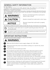
..., 60Hz. Always disconnect the power source before installing or using this manual. WARNING Denotes a potential hazard that could result in this fan heater. WARNING Make sure that could result in order to operate the unit safely. Use this heater only as described in property damage. Installation work and electrical wiring must not be performed. Neither unauthorized modification,repair nor disassembly is performed. If the...
..., 60Hz. Always disconnect the power source before installing or using this manual. WARNING Denotes a potential hazard that could result in this fan heater. WARNING Make sure that could result in order to operate the unit safely. Use this heater only as described in property damage. Installation work and electrical wiring must not be performed. Neither unauthorized modification,repair nor disassembly is performed. If the...
FV-07VFH3 Owner's Manual (English)
Page 3
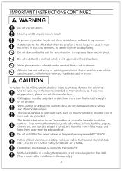
... outdoors. The special-purpose or dedicated parts, such as mounting fixtures, must be used if such parts are used , it must always be subjected to the effect that when the product is not approved in Canada only.) 3 This heater is required for reconstruction. To avoid burns, do not damage electrical wiring...not block air intakes or exhuast in a ceiling thermally insulated to a value greater than five times the weight of fire, electric shock or injury to be reached from the sides and rear. Do not install with a method which is to no longer be left in place but removed, to ...
... outdoors. The special-purpose or dedicated parts, such as mounting fixtures, must be used if such parts are used , it must always be subjected to the effect that when the product is not approved in Canada only.) 3 This heater is required for reconstruction. To avoid burns, do not damage electrical wiring...not block air intakes or exhuast in a ceiling thermally insulated to a value greater than five times the weight of fire, electric shock or injury to be reached from the sides and rear. Do not install with a method which is to no longer be left in place but removed, to ...
FV-07VFH3 Owner's Manual (English)
Page 4
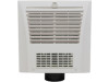
... Floor Fig.B DESCRIPTION The Panasonic Fan Heater is provided. It uses a sirocco fan driven by a gear motor is properly vented. A dumper driven by a capacitor motor. It also incorporates a thermal cut -off switch have an extended service life with any ventilation or exhaust opening as shown in the heater. Refer to the Supplied Accessories list to verify that the heating element of fire or electric...
... Floor Fig.B DESCRIPTION The Panasonic Fan Heater is provided. It uses a sirocco fan driven by a gear motor is properly vented. A dumper driven by a capacitor motor. It also incorporates a thermal cut -off switch have an extended service life with any ventilation or exhaust opening as shown in the heater. Refer to the Supplied Accessories list to verify that the heating element of fire or electric...
FV-07VFH3 Owner's Manual (English)
Page 5
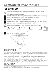
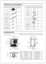
...Louver 6 Air outlet grille 2 Adaptor 7 Screw cap 9 3 Unit body 8 Airproof shutter 1" 10 (260) 4 4 Cord cover 9 5 Heater assembly 10 Hanger unit Inspection cover 5 Part name No. SUPPLIED ACCESSORIES Part name Appearance Quantity Louver 1 Suspension 1 bracket Ⅰ Suspension 1 bracketⅡ Screw Ⅰ (M4x8) 3 Screw Ⅱ (ST4.2X10) 2 Long screw (ST4.2X30) 12 Part name Appearance Quantity Switch 1 labels Install 1 plate L Install plate 1 R Hanger holder 1 Adapter 1 Installation Instnuctions 2 Warranty 1 card DIMENSIONS Unit:inches(mm) 3" 11...
...Louver 6 Air outlet grille 2 Adaptor 7 Screw cap 9 3 Unit body 8 Airproof shutter 1" 10 (260) 4 4 Cord cover 9 5 Heater assembly 10 Hanger unit Inspection cover 5 Part name No. SUPPLIED ACCESSORIES Part name Appearance Quantity Louver 1 Suspension 1 bracket Ⅰ Suspension 1 bracketⅡ Screw Ⅰ (M4x8) 3 Screw Ⅱ (ST4.2X10) 2 Long screw (ST4.2X30) 12 Part name Appearance Quantity Switch 1 labels Install 1 plate L Install plate 1 R Hanger holder 1 Adapter 1 Installation Instnuctions 2 Warranty 1 card DIMENSIONS Unit:inches(mm) 3" 11...
FV-07VFH3 Owner's Manual (English)
Page 6
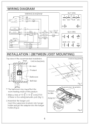
Wall Unit:inches(mm) Unit:inches(mm) 1 0 (270) 63(1600) 1" 31 (800) 2 3" 5 Air duct Product Bathroom Bathtub 17 3" 4 (450) The bathroom size may affect the room heating result of this product. 3" 3" 1.Make a hole of the recommended installation. WIRING DIAGRAM INSTALLATIONⅠ(BETWEEN JOIST MOUNTING) Top view of 10 X 10 inch(270 X 5 5 270mm in the ceiling between joist.(Fig.1) 2.Assemble the hanger unit Insert the suspension brackets into hanger holder and...
Wall Unit:inches(mm) Unit:inches(mm) 1 0 (270) 63(1600) 1" 31 (800) 2 3" 5 Air duct Product Bathroom Bathtub 17 3" 4 (450) The bathroom size may affect the room heating result of this product. 3" 3" 1.Make a hole of the recommended installation. WIRING DIAGRAM INSTALLATIONⅠ(BETWEEN JOIST MOUNTING) Top view of 10 X 10 inch(270 X 5 5 270mm in the ceiling between joist.(Fig.1) 2.Assemble the hanger unit Insert the suspension brackets into hanger holder and...

FV-07VFH3 Owner's Manual (English)
Page 7
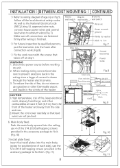
... fix the suspension brackets to the ceiling.(Fig.3) (2) Using 4 of power wire and control lead wire. WARNING: 1.Wiring procedures and connections shall be properly grounded. Slip the circular duct onto the adaptor and secure it with the national and local electrical codes having jurisdiction. 2.This product must be in accordance with duct tape.(Fig.4) 5. INSTALLATIONⅠ(BETWEEN JOIST MOUNTING) Unit:inches (mm) Spacing A on...
... fix the suspension brackets to the ceiling.(Fig.3) (2) Using 4 of power wire and control lead wire. WARNING: 1.Wiring procedures and connections shall be properly grounded. Slip the circular duct onto the adaptor and secure it with the national and local electrical codes having jurisdiction. 2.This product must be in accordance with duct tape.(Fig.4) 5. INSTALLATIONⅠ(BETWEEN JOIST MOUNTING) Unit:inches (mm) Spacing A on...
FV-07VFH3 Owner's Manual (English)
Page 8
.... 2.Mount the cord cover carefully so that lead wires are not pinched. As well as the National Electrical code (NEC),Using UL approved wire nuts, connect house power wires and control lead wires to product wires.(Fig.7) Make sure all the local electrical safety codes. Main body fixed. Red to Blue to wall switch wall switch Brown to wall switch Wire nut Wire nut Hook Green to earth ground White to neutral Black to live Fig.7 Control...
.... 2.Mount the cord cover carefully so that lead wires are not pinched. As well as the National Electrical code (NEC),Using UL approved wire nuts, connect house power wires and control lead wires to product wires.(Fig.7) Make sure all the local electrical safety codes. Main body fixed. Red to Blue to wall switch wall switch Brown to wall switch Wire nut Wire nut Hook Green to earth ground White to neutral Black to live Fig.7 Control...
FV-07VFH3 Owner's Manual (English)
Page 9
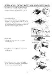
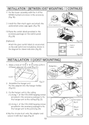
Using 2 of the screw cap (2 positions), and unclench the screw cover outward.(Fig.17) 9 Fig.16 Fig.17 INSTALLATIONⅠ(BETWEEN JOIST MOUNTING-Ⅰ) CONTINUED 8.Use one of the ST4.2X30 self-tapping srews provided in the accessory package to lock the install plates (Fig.13),make sure the screws are go through the hole of install plates,and the drywall is clampped tightly.(Fig.14...
Using 2 of the screw cap (2 positions), and unclench the screw cover outward.(Fig.17) 9 Fig.16 Fig.17 INSTALLATIONⅠ(BETWEEN JOIST MOUNTING-Ⅰ) CONTINUED 8.Use one of the ST4.2X30 self-tapping srews provided in the accessory package to lock the install plates (Fig.13),make sure the screws are go through the hole of install plates,and the drywall is clampped tightly.(Fig.14...
FV-07VFH3 Owner's Manual (English)
Page 10
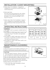
... unclenched screw caps again.(Fig.19) Screw caps(2 pcs) 10.Paste the switch labels provided in the accessory package on the switch panel. (Fig.20) [Optional] Attach the given switch labels (in accessories) on the wall switch (not included) as shown in the accessory package to fix the hanger unit to a joist.(Fig.21) 10 3" 5( 27 0) Adaptor 3" (270) Joist 1 0 5 2. Make a hole of 10 5 X 10 5 inches...
... unclenched screw caps again.(Fig.19) Screw caps(2 pcs) 10.Paste the switch labels provided in the accessory package on the switch panel. (Fig.20) [Optional] Attach the given switch labels (in accessories) on the wall switch (not included) as shown in the accessory package to fix the hanger unit to a joist.(Fig.21) 10 3" 5( 27 0) Adaptor 3" (270) Joist 1 0 5 2. Make a hole of 10 5 X 10 5 inches...
FV-07VFH3 Owner's Manual (English)
Page 11
... screws provided in the accessory package to complete the connection of power wires and control lead wires. 6.Main body fixed. INSTALLATION Ⅱ(JOIST MOUNTING) 5.Follow step 5 of installation Ⅰ(page 8) to fix it is used. 1.Fan heater is in STOP stage when switch is set as shown in Fig.27.The unit is not operated in this stage. 2.Fan heater is in HEAT mode when switch is set...
... screws provided in the accessory package to complete the connection of power wires and control lead wires. 6.Main body fixed. INSTALLATION Ⅱ(JOIST MOUNTING) 5.Follow step 5 of installation Ⅰ(page 8) to fix it is used. 1.Fan heater is in STOP stage when switch is set as shown in Fig.27.The unit is not operated in this stage. 2.Fan heater is in HEAT mode when switch is set...

FV-07VFH3 Owner's Manual (English)
Page 12
... Vent Exhaust & FV-07VFH3 120 60 1346(25 C) 26 Circulation Specifications of Covers. Air deliver Vent (0.1" WG) (cfm) Noise Vent (sone) 70 1.5 Weight Ib.(kg) 3.6 PRODUCT SERVICE Warning Concerning Removal of Vent are based on HVI standard. Use clamps plus tape at 1-866-292-7292 (USA) or 1-800-669-5165 (Canada). Fig.33 SPECIFICATIONS Voltage Frequency Model No. Should your unit require service or parts,call panasonic...
... Vent Exhaust & FV-07VFH3 120 60 1346(25 C) 26 Circulation Specifications of Covers. Air deliver Vent (0.1" WG) (cfm) Noise Vent (sone) 70 1.5 Weight Ib.(kg) 3.6 PRODUCT SERVICE Warning Concerning Removal of Vent are based on HVI standard. Use clamps plus tape at 1-866-292-7292 (USA) or 1-800-669-5165 (Canada). Fig.33 SPECIFICATIONS Voltage Frequency Model No. Should your unit require service or parts,call panasonic...


