FV-07VFH3 Owner's Manual (English)
Page 2
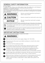
...symbol word panels are used to alert users to a specific operating procedure that could result in this manual. Before servicing or cleaning unit, switch power off at service panel and have heater inspected by a reputable electrician before reusing. NOTICE Denotes a hazard that must be followed in... is AC 120V, 60Hz. The following safety precautions. Disconnect power at service panel and lock panel cabinet to prevent power from being switched on or near the fan, motor or junction box. GENERAL SAFETY INFORMATION For Your Safety To reduce the risk of injury, loss...
...symbol word panels are used to alert users to a specific operating procedure that could result in this manual. Before servicing or cleaning unit, switch power off at service panel and have heater inspected by a reputable electrician before reusing. NOTICE Denotes a hazard that must be followed in... is AC 120V, 60Hz. The following safety precautions. Disconnect power at service panel and lock panel cabinet to prevent power from being switched on or near the fan, motor or junction box. GENERAL SAFETY INFORMATION For Your Safety To reduce the risk of injury, loss...
FV-07VFH3 Owner's Manual (English)
Page 3
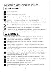
... that when the product is to persons, observe the following: Use this fan heater where air temperature may cause fire or electric shock. Never place a switch where it in the manner intended by the manufacturer. This heater is hot when in place but removed, to static load more than R40. (This...
... that when the product is to persons, observe the following: Use this fan heater where air temperature may cause fire or electric shock. Never place a switch where it in the manner intended by the manufacturer. This heater is hot when in place but removed, to static load more than R40. (This...
FV-07VFH3 Owner's Manual (English)
Page 4
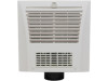
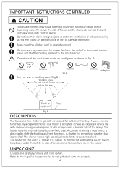
... is screw-fixed type. Make sure that all parts are configured as this area Prohibition Adaptor 45 45 Cooking equipment Floor Fig.B DESCRIPTION The Panasonic Fan Heater is designed to shift the heating and vent functions. Do not install the unit where ducts are present. 4 It also incorporates ...a thermal cut -off switch have an extended service life with any ventilation or exhaust opening as shown in the heater. Refer to the Supplied Accessories list to have been...
... is screw-fixed type. Make sure that all parts are configured as this area Prohibition Adaptor 45 45 Cooking equipment Floor Fig.B DESCRIPTION The Panasonic Fan Heater is designed to shift the heating and vent functions. Do not install the unit where ducts are present. 4 It also incorporates ...a thermal cut -off switch have an extended service life with any ventilation or exhaust opening as shown in the heater. Refer to the Supplied Accessories list to have been...
FV-07VFH3 Owner's Manual (English)
Page 5
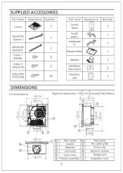
... Appearance Quantity Louver 1 Suspension 1 bracket Ⅰ Suspension 1 bracketⅡ Screw Ⅰ (M4x8) 3 Screw Ⅱ (ST4.2X10) 2 Long screw (ST4.2X30) 12 Part name Appearance Quantity Switch 1 labels Install 1 plate L Install plate 1 R Hanger holder 1 Adapter 1 Installation Instnuctions 2 Warranty 1 card DIMENSIONS Unit:inches(mm) 3" 11 (295) 5 3" 6 (160) 10 3" 3" Aperture dimensions: 10 x10 inches...
... Appearance Quantity Louver 1 Suspension 1 bracket Ⅰ Suspension 1 bracketⅡ Screw Ⅰ (M4x8) 3 Screw Ⅱ (ST4.2X10) 2 Long screw (ST4.2X30) 12 Part name Appearance Quantity Switch 1 labels Install 1 plate L Install plate 1 R Hanger holder 1 Adapter 1 Installation Instnuctions 2 Warranty 1 card DIMENSIONS Unit:inches(mm) 3" 11 (295) 5 3" 6 (160) 10 3" 3" Aperture dimensions: 10 x10 inches...
FV-07VFH3 Owner's Manual (English)
Page 8
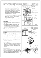
... to live Fig.7 Control lead wines Power wires Green wire From red wire From blue wire From brown wire Fig.8 ON/OFF HEAT/VENT (wall switch) Green White N L Black E Fig.9 6. To reduce the risk of fire, do not store or use gasoline or other flammable vapors and liquids in the ...product wires.(Fig.7) Make sure all the local electrical safety codes. Disconnect power source before working on unit. 2. Red to Blue to wall switch wall switch Brown to wall switch Wire nut Wire nut Hook Green to earth ground White to neutral Black to prevent excessive slack in the wiring since a layge of...
... to live Fig.7 Control lead wines Power wires Green wire From red wire From blue wire From brown wire Fig.8 ON/OFF HEAT/VENT (wall switch) Green White N L Black E Fig.9 6. To reduce the risk of fire, do not store or use gasoline or other flammable vapors and liquids in the ...product wires.(Fig.7) Make sure all the local electrical safety codes. Disconnect power source before working on unit. 2. Red to Blue to wall switch wall switch Brown to wall switch Wire nut Wire nut Hook Green to earth ground White to neutral Black to prevent excessive slack in the wiring since a layge of...
FV-07VFH3 Owner's Manual (English)
Page 10
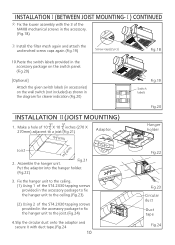
...0 5 2. INSTALLATIONⅠ(BETWEEN JOIST MOUNTING-Ⅰ) CONTINUED ④ Fix the louver assembly with duct tape.(Fig.24 10 Vent Off Fig.18 Fig.19 Switch labels Fig.20 Hanger holder Fig.22 Fig.23 Circular duct Duct tape Fig.24 Assemble the hanger unit. Make a hole of the M4X8 mechanical...the unclenched screw caps again.(Fig.19) Screw caps(2 pcs) 10.Paste the switch labels provided in the accessory package on the switch panel. (Fig.20) [Optional] Attach the given switch labels (in accessories) on the wall switch (not included) as shown in the diagram for clearer indication.(Fig.20) On...
...0 5 2. INSTALLATIONⅠ(BETWEEN JOIST MOUNTING-Ⅰ) CONTINUED ④ Fix the louver assembly with duct tape.(Fig.24 10 Vent Off Fig.18 Fig.19 Switch labels Fig.20 Hanger holder Fig.22 Fig.23 Circular duct Duct tape Fig.24 Assemble the hanger unit. Make a hole of the M4X8 mechanical...the unclenched screw caps again.(Fig.19) Screw caps(2 pcs) 10.Paste the switch labels provided in the accessory package on the switch panel. (Fig.20) [Optional] Attach the given switch labels (in accessories) on the wall switch (not included) as shown in the diagram for clearer indication.(Fig.20) On...
FV-07VFH3 Owner's Manual (English)
Page 11
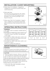
... for cleaning the ventilating fan. 2.Do not allow any water to get into bathroom. The bathroom become warm. 3.Fan heater is in VENT mode when switch is set as ahown in the figure (Fig.30). 11 Vent Off Heat On Fig.28 Vent Off Heat On Fig.25 Joist Fig.26... set as shown in Fig.27.The unit is not operated in this stage. 2.Fan heater is in HEAT mode when switch is set as shown in Fig.28.The unit blown out hot air. OPERATING INSTRUCTIONS WARNING The heater shall be done every year. Heat On ...
... for cleaning the ventilating fan. 2.Do not allow any water to get into bathroom. The bathroom become warm. 3.Fan heater is in VENT mode when switch is set as ahown in the figure (Fig.30). 11 Vent Off Heat On Fig.28 Vent Off Heat On Fig.25 Joist Fig.26... set as shown in Fig.27.The unit is not operated in this stage. 2.Fan heater is in HEAT mode when switch is set as shown in Fig.28.The unit blown out hot air. OPERATING INSTRUCTIONS WARNING The heater shall be done every year. Heat On ...