Panasonic CF-72X3UUBDM - Toughbook 72 - Pentium 4-M 1.8 GHz Support and Manuals
Get Help and Manuals for this Panasonic item
View All Support Options Below
Free Panasonic CF-72X3UUBDM manuals!
Problems with Panasonic CF-72X3UUBDM?
Ask a Question
Free Panasonic CF-72X3UUBDM manuals!
Problems with Panasonic CF-72X3UUBDM?
Ask a Question
Popular Panasonic CF-72X3UUBDM Manual Pages
Service Manual - Page 1

... E: Microsoft Windows 98
Drive B: CD-ROM drive C: CD-ROM drive / SuperDisk drive
WARNING
This service information is designed for experienced repair technicians only and is the Service Manual for Spain
Model Number Reference
The models in the CF-72 series are numbered in attempting to advise non-technical individuals of law. It does not contain...
Service Manual - Page 5

... is achieved by using the dithering function. *2 1GB = 109 bytes
1 - 1
Specifications
This page provides the specifications for CF-72xxxxxCx)
*1 A 16M color display is confirmed in [System Memory] of the computer or the box the computer came in [Start] - [Programs] - [Panasonic] - [DMI Viewer]. The model number will change depending on the configuration of the [Main] menu...
Service Manual - Page 6

... is off. Other Specifications
Keyboard
87 keys
SuperDisk Drive
720 KB/1.44 MB/120MB (for CF 72xxxCxxx)
CD-ROM...built in) x 4
Utility Programs
Setup Utility, DMI Viewer, Panasonic Hand Writing*4
Sound
Battery Pack
HRTF 3D positional audio support 16-bit stereo, WAVE and MIDI... compatible with power sources up from LAN] has been enabled (models with a 125 V AC compatible AC cord.
*8 Approx....
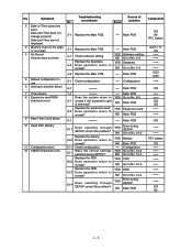
Service Manual - Page 13

...
The basic procedures for conduct trouble diagnosis. For details, refer to symptoms.
REPAIR WORK
DISASSEMBLY PROCEDURE Replace defective parts. TROUBLESHOOTING Defective parts are summarized below. POST NORMAL FINISH
POST ERROR OCCURRENCE
DEFECTIVE PARTS SORTING
SELF-DIAGNOSIS TEST (IF REQUIRED) Conduct a self diagnosis test when it is set to ON.
INSPECTION
SELF-DIAGNOSIS...
Service Manual - Page 15
... and contact Panasonic Technical Support. If the error persists, check the system battery or contact Panasonic Technical Support. 0260 System timer error The timer test failed. run SETUP Type of the messages that the diskette drive is dead - If you make changes in the Setup menus, reset the computer, enter Setup and install Setup defaults or correct the error.
0200 Failure...
Service Manual - Page 16

... Contact Panasonic Technical Support. 02F0: CPU ID: CPU socket number for offset address of the bits at the RAM address which failed the memory test. Failing Bits : nnnn The hex number nnnn is a method for : device Run ISA or EISA Configuration Utility to enter a Setup and change the settings. I/O device IRQ conflict I /O bus. Allocation Error...
Service Manual - Page 18
... card. NO Main PCB
9-1
Main PCB
10 Dead RTC Battery
11 Configuration error 12 CMOS Checksum error
10-1
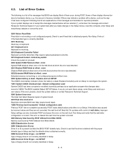
Does resetting through SETUP correct the problem? Check configuration.
No.
Troubleshooting
No. YES Software setting NO Go to normal? Does operation return to
normal?
Replace the HDD.
YES Expansion card
8-2 Does operation return to normal?
Symptom
2 Date...
Service Manual - Page 19

... display properly after brightness
YES
Brigntness adjustment
level is not updating
14 Memory size/data error
15 PCI failur
No. 13-1
14-1
15-1 15-2
Troubleshooting procedures
Does resetting the date/time in SETUP correct the problem? Does operation return to
normal? Display quality poor. Replace the LCD.
Replace the Inverter PCB.
YES Main PCB
3-2 Does operation return...
Service Manual - Page 20

... the keyboard setting in the operating system correct?
NO
Keyboard was not connected
properly
Replace the keyboard.
Key top does not spring back after pressing.
2 None of problem
1-1 Keyboard is displayed as grabage.
4 Mouse does not function. Inputs from the track ball are not accepted properly.
6 Keyboard failure
7 Keyboard interface failure
Troubleshooting
No. Input...
Service Manual - Page 23

... test? YES NO
Go to No. 8-2
Replace the HDD. YES Main PCB NO Improper setting
Component
IC5 IC30
IC5 IC30
IC5 IC30 IC5 IC30
4 - 11
Troubleshooting
No.
NO Main PCB
3-1
Is the COM port properly set for both the
sending and receiving units?
Symptom
Troubleshooting
No. procedures
Result
Source of problem
1-1
Is the COM port properly...
Service Manual - Page 24

....
NO Go to
normal? No. procedures
Result
problem
Replace the CD-ROM drive.
YES LED PCB
1-2 Does operation return to No. 1-3
Replace the Main PCB. YES CD-ROM drive
2-2 ...Does the printer pass its self-printing test? Troubleshooting
Source of
No.
4.4.8.
NO CD-ROM drive
Component LD703 IC3
IC3 IC3
4 - 12 Troubleshooting
No.
NO Go to No. 2-2 Printer
...
Service Manual - Page 25

... electronic
NO
Change operating environment
equipment? Troubleshooting
No.
NO Improper setting
2
Transmitted data becomes corrupted.
2-1
Is the transmission distance within specified distance
Is the transmisson path YES Main PCB clear of problem
1-1
Is the Infrared Communication Port enabled in Setup?
procedures
Result
Source of obstacles and
interference...
Service Manual - Page 26
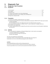
...The System Setup should be set to the mouse port. 3) Power on the LCD. (3) The serial port must be invoked
by executing the "SETUP UTILITY" ...password and disable the password.
5 - 1 Do not use "Password Skipping Plug" in order to skip the user password. 1) Connect the parallel plug to the parallel port. 2) Connect the PS/2 mouse plug to the factory setting...servicing purpose only.
5.
Service Manual - Page 68
...FOR CONNECTOR (B) PC
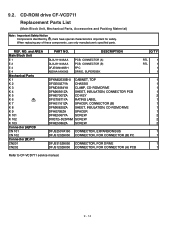
DFJS315ZA050 CONNECTOR, FOR DRIVE DFJS120ZA050 CONNECTOR, FOR CONNECTOR (A) PCB
Refer to CF-VCD711 service manual. When replacing any of these components, use only manufacturer's specified parts. CD-ROM drive CF-VCD711
Replacement Parts List
(Main Block Unit, Mechanical Parts, Accessories and Packing Materrial)
Note: Important Safety Notice Components identified by mark have...
Service Manual - Page 69

... KEY
2
RATING LABEL
1
WASHER
4
SCREW
4
SCREW
4
CONNECTOR, EXPANSION BUS
1
CONNECTOR, FOR CONNECTOR (B) PCB
1
RESISTOR, 1/16W, 0
2
CONNECTOR, FOR CONNECTOR (A) PCB
1
CONNECTOR, FOR DRIVE
1
Refer to CF-VFS712W service manual.
9 - 15
NO. When replacing any of these components, use only manufacturer's specified...
Panasonic CF-72X3UUBDM Reviews
We have not received any reviews for Panasonic yet.